TUNABLE SOURCES: Tunable multiwavelength grid laser exploits nonlinear optical effects
NIMA AHAMADVAND AND ERIC WETJEN
A new technique has been developed by Peleton that utilizes nonlinear effects in optical fiber to produce evenly spaced wavelengths with a variety of channel spacings (such as 50 or 100 GHz) common in today’s telecommunication networks.1 The multiwavelength grid is tuned to allow operation with frequency offsets of, for example, up to one-quarter of the channel spacing.
The process starts with two distributed-feedback (DFB) seed lasers and uses an innovative multiplier technology to simultaneously produce a large number of wavelength channels. With a single wavelength-locking mechanism, the whole set of channels can be tuned to a predefined wavelength grid such as the International Telecommunication Union (ITU) grid. Temperature and current tuning of the DFB seed lasers allows the wavelengths to be locked to frequencies that are offset from the ITU grid. In the case of a multiwavelength laser that tunes up to one-quarter of the channel spacing, the entire wavelength comb can be made to scan from ITU minus 25 GHz to ITU plus 25 GHz. Designed for flexibility as a source for test and measurement applications, this tunability feature adds the advantage of narrowband tuning to those advantages already existing from the simultaneous availability of multiple wavelengths.
This tunable-grid concept can provide wavelength channels in the S (1485–1520 nm), C (1530–1562 nm), and L (1570–1610 nm) bands, with the channel spacing determined by the frequency spacing of the seed lasers. A tunable multiwavelength laser is a low-cost alternative to banks of individual lasers needed to test advanced optical network equipment and can replace tunable single lasers in many test applications.
Multiwavelength laser architecture
The evolution and creation of the tunable multiwavelength spectrum is explained by following the optical signal from two DFB seed lasers in an optical setup (see Fig. 1). An attenuator in the measurement setup protects the optical spectrum analyzer (OSA) from excessive optical power so actual power levels for the spectrum are higher than those displayed by the OSA traces.
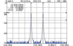
The process of generating a multiwavelength spectrum with predefined channel spacing begins with the combination of two seed-laser signals to form a beat signal, which is a sinusoidal modulation observed at the frequency separation of the two seeds (see Fig. 2).
For C-band operation at 100-GHz channel spacing, the laser seed wavelengths of 1546.119 and 1546.916 nm are chosen because they are close to the center of the desired band to provide better power-distribution uniformity among generated channels. To avoid loss of optical power, the two seed wavelengths are combined by a polarization-maintaining combiner. This beat signal is then sent to a high-power optical amplifier, specially designed to reduce spontaneous emission and to emphasize amplification of the seed lasers (see Fig. 3). Additional frequencies begin to appear when the beat signal is amplified. The two additional frequencies that appear are at 100 GHz on either side of the two seed lasers (at 1545.32 and 1547.72 nm) and can be explained by degenerate four-wave mixing, a nonlinear optical phenomenon in which the fiber medium allows two laser frequencies to interact with one another and produce new frequencies.
At this point, there are four waves at four different frequencies. Now, if the power in the four waves is sufficient, the general case of four-wave mixing applies, provided there is a medium for the nonlinear effects to take place. This results in a chain reaction that eventually produces the entire grid of wavelengths, all separated by the channel spacing of the original seed lasers.
For this chain reaction to occur, the high-power amplifier boosts the optical power to more than 1 W. This high-power signal enters the multiplier module in which the remaining grid wavelengths are generated. The multiplier consists of several sections of optical fiber with carefully chosen dispersive and nonlinear properties. Channel multiplication (in number) results from nonlinear effects, including self-phase modulation, cross-phase modulation, and four-wave mixing on the high-power beat signal. Even though all the nonlinear effects are in play right at the input end of the multiplier, self-phase modulation and cross-phase modulation are the dominant effects in the beginning that perform pulse compression on the beat signal. This compression produces very short pulses with very high peak power, which enhance the nonlinear effects-especially four-wave mixing. As a result, four-wave mixing gradually becomes the dominant nonlinear effect, and new channels are created.
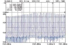
The multiplier must be optimized to provide a flat spectrum profile at the output for a specific wavelength band. To cover a specific band, the seed lasers must have wavelengths in the center of the target band. Then, the dispersion properties of the different sections of the multiplier must be optimized to that wavelength band. With these conditions met, a coherent multiwavelength source can be generated, with tunability achieved by temperature and current tuning of the seed lasers. The output spectrum of a multiplier designed for 100-GHz channel spacing can have a total power of about 400 mW (see Fig. 4).
Simple spectrum shaping can provide better power uniformity in the whole band by cutting the power of all the channels to the same level as the smallest channel power in the set. However, by doing so, the total power and the power per channel are drastically reduced. To apply spectrum shaping and simultaneously keep the output power high, a booster amplifier is used. In this case, the spectrum shaping considers not only the output spectrum profile of the multiplier, but also the gain profile of the booster amplifier.
The spectral shaping and booster amplification results in a 40-channel multiwavelength laser source that covers the C band with 100-GHz channel spacing (see Fig. 5). The output power is 200 mW, or about 5 mW per channel.
Wavelength locking
Control of the seed lasers allows control of the entire grid. The seed-laser wavelengths are controlled using the wavelengths of the edge channels in the output channel set. Any error in the wavelength settings of the two seed lasers is amplified at the edges of the output channel set, so this method ensures much tighter wavelength locking than that of single lasers. For example, if the seed lasers are separated nominally by 100 GHz and they can each be controlled to within ± 1.25 GHz (achievable with commercially available wavelength lockers), then the frequency separation could be as much as 102.5 GHz in the worst case. Now as four-wave mixing takes place, the channels farthest from the seed wavelengths will have errors that are a multiple of the original error in the frequency spacing of the seeds.
With a 40-channel system, the channels at the edges that are 19 channel spacings away from the seeds will be 19 × 102.5 GHz away from the seed wavelength. This results in an absolute frequency error of 47.5 GHz, which is nearly half of the channel spacing-an unacceptably large error. To avoid this problem, the seed lasers are adjusted based on feedback from frequencies at the outermost channels. If we use Channel 1 at 1529.55 nm and Channel 40 at 1560.61 nm and we have the same locking accuracy as above, then these edge channels will be at 192100 ± 1.25 GHz and 196000 ± 1.25 GHz, respectively. It follows that the frequency spacing of the grid will be at worst case 100.05 GHz (3902.5 GHz/39), which is much better than that achievable with a control signal based on the laser seed frequencies. It also provides a means to lock the entire wavelength comb using only two wavelength lockers. As a result, wavelength accuracy on the order of ±10 pm is possible throughout the output channel set.
To provide tunability, the wavelength-locking algorithm is calibrated using a lookup table to lock the edge channels to a particular offset value. Because all the channels move together, the entire grid will move to the offset value. Because of optical filtering used in the current implementation of the optical train, the comb tuning is limited to a fraction (±1/4) of the channel spacing. A tunable multichannel laser source that covers half the channel spacing is feasible and would provide tunability across the entire band.
Applications
The multiwavelength laser source described here has applications in test and measurement of wavelength-selective subsystems in research and manufacturing settings. Specific applications include testing of reconfigurable optical add/drop multiplexers (ROADMs), photonic switches, and embedded optical-performance monitors. The source also enables per-channel gain and noise-figure measurements of optical amplifiers, and evaluation of full-channel system-loading effects. In addition, for applications in research and development, this source offers significant cost and size reductions when compared to more traditional banks of DFB lasers. The fact that all channels are available simultaneously provides the added advantage of reduced measurement time when compared to stepping a tunable laser across the channel spectrum.
REFERENCE
1. Canadian patent 2,365,076 (May 11, 2004) and United States patent 6,826,207 (Nov. 30, 2004).
Nima Ahamadvand is vice president of research and development and Eric Wetjen is director of product management at Peleton, 2355 St. Laurent Blvd., Ottawa, Ontario, Canada K1G 6C3; e-mail: [email protected]; www.peleton.com.


