The ‘miniature’ gyroscope evolves
Nineteenth-century physicist Leon Foucault applied the name “gyroscope” to a wheel or rotor mounted in gimbal rings that can turn freely in any direction. While Foucault used the gyroscope as a tool to study Earth’s rotation, it was Elmer Ambrose Sperry who, in 1908, deployed the first workable gyrocompass system that played a major role in ship navigation during World War I and II.
While the size of those early navigational gyroscopes was not a problem for Navy ships, aircraft demanded lighter and smaller instrumentation. In the 1950s and early 1960s, the Sperry Gyroscope Company, Honeywell, and other companies and institutions began developing and refining the ring-laser gyroscope.
The changing definition of ‘miniature’
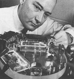
In the very first issue of Laser Focus magazine (Jan. 1, 1965, p.15), the Military Products Group of Honeywell introduced what it called a “miniature” laser gyro in a story, “Miniature laser integrating gyro bows in.” The gyro weighed 8 lb (see figure). The operating principle of a ring-laser gyroscope was briefly described as the conversion of an optical-path-length difference between clockwise- and counterclockwise-propagating beams of a laser during angular rotation into directional information. “Although this basic principle has been known for some time, it took the advent of the laser to convert the concept from an intellectual curiosity to a design configuration with practical potentials,” noted the Laser Focus editor. “The unit’s very small size and low potential cost of $1000 or less per unit add to its attractiveness.”
Defining an 8-lb gyroscope as “miniature” in 1965 was not unwarranted, especially considering that spinning-mass mechanical gyroscopes of the time could weigh 100 lb or more. But even though this Honeywell laser gyroscope model was lightweight in comparison, it still used bulky glass prisms to form the triangular cavity, and a helium-neon laser beam discharge provided by radio-frequency (RF) or direct-current (DC) pumping of two gain tubes 10-cm long.
It was not until the early 1990s that the first fiberoptic gyroscopes (FOGs) became sophisticated enough for commercial deployment. Whether they were resonant FOGs (RFOGs), which used a short loop of fiber and a narrowband laser source, or interferometric FOGs (IFOGs), which used a longer length of fiber and a light-emitting-diode source, these FOGs offered a robust, smaller package with solid-state light sources and considerably lower production cost.1

null
Because FOGs have many classifications (military grade, tactical grade, instrument grade, for example), a variety of configurations (single axis for measuring rotation rate and angular position about a single axis, dual axis for measuring pitch and roll, and three axis for measuring the full rotation-rate vector), and different packaging options (optical portion only, or full packaging with sensor electronics and power supply), it is difficult to compare their physical and performance specifications to earlier gyroscope types. However, the 1965-era laser integrating gyros would today be comparable in performance to Northrop Grumman Navigation Systems’ (Woodland Hills, CA) model LN-200 Inertial Measurement Unit (IMU) with bias repeatability performance of 1°/h to 10°/h, dimensions of roughly 3.5 sq in., and an overall weight of less than 1.65 lb.
In addition to Northrop Grumman Navigation Systems (formerly Litton Guidance and Control Systems), current manufacturers of FOGs include Sperry Marine Northrop Grumman (formerly Sperry Gyroscope Company and Sperry Rand; Charlottesville, VA), Honeywell (Morristown, NJ), L-3 Electronic Systems (Toronto, ON, Canada), and KVH (Middletown, RI), among many others.
Even smaller yet
Today, FOGs are continually evolving and enjoying further size reduction because of various technological advances. In May 2002, KVH was awarded U.S. patent 6,351,310 for a “Reduced minimum configuration interferometric FOG with simplified signal processing electronics.” Further FOG performance improvements and size reductions have been made through better optical-fiber designs (see Military & Aerospace Electronics, Optoelectronics Design supplement, January 2004, p. 17) and improved optical integration techniques (see Laser Focus World, Optoelectronics Manufacturing supplement, July 2005, p. S3). But now FOGs are challenged by even smaller microelectromechanical systems (MEMS)-based gyroscopes in several applications.
Unlike FOGs that use the basic optical principles of ring-laser gyroscopes, MEMS-based gyros use vibrating mechanical elements to sense rotation. These vibratory gyroscopes are based on the energy transfer between two vibration modes of a structure caused by the Coriolis acceleration that arises in a rotating reference frame and is proportional to the rate of rotation.2 Different types of MEMS-based gyros include silicon vibratory gyroscopes manufactured by Robert Bosch (Stuttgart, Germany) and Silicon Sensing Systems (Amagasaki, Japan; a joint-venture of Sumitomo and BAE Systems) and quartz vibratory gyroscopes from BEI Systron Donner (Concord, CA).
Silicon and quartz gyroscope technologies are primarily used for automotive applications, with pricing on the order of $60 for gyroscopes in applications such as vehicle dynamic control and navigation assist. Gyroscopes for less-demanding applications like rollover detection cost even less. Another MEMS category, again primarily for automotive applications, is based on a modified tuning-fork design, and is manufactured by Analog Devices (Norwood, MA).
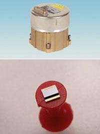
Because of major investment in the MEMS industry during the telecom bubble, MEMS-based products, including gyroscopes, have benefited from wafer-scale integration and packaging technologies. Steven Nasiri of InvenSense (Santa Clara, CA), a 26-year veteran of the MEMS industry, predicts that when gyroscope pricing is able to reach the $2-per-axis range, a host of new applications will emerge. InvenSense has developed what it says is perhaps the tiniest MEMS-based integrated dual-axis gyroscope targeted for use in mass-market consumer applications. Its compact size and low price will help drive adoption of gyroscopes for such cost-sensitive applications as digital and cell-phone camera image stabilization and gesture-based controls for user interfaces and game controllers.
While many are skeptical that a $2-per-axis price range can be achieved, gyroscopes that are even smaller than current MEMS devices are already in development. Late last year, researchers at Sandia National Laboratories (Albuquerque, NM) demonstrated a laterally deformable optical nanoelectromechanical system, with potentially low-cost fabrication using standard lithography processes, that is being targeted for such practical applications as inertial navigation (see Laser Focus World, December 2004, p. 23). Although these devices are three to five years away, a packaged gyroscope with submillimeter dimensions could be possible. It will be interesting to see just how small the gyroscopes developed beyond 2005 will be-without a microscope, we may not be able to see them at all.❏
REFERENCES
1. N. M. Barbour et al., American Inst. Aeronautics and Astronautics (AIAA) Guidance, Navigation and Control Conf., tech.papers pt. 2 (A92-55151 23-63) (Hilton Head Island, SC; Aug. 10-12, 1992).
2. S. Nasiri, Sensors Expo, Anaheim, CA, invited paper, (Sept. 24, 2003).