DISK LASERS: YAG is redefined through the diode-pumped disk laser
What makes diskgeometry so ideal and how does disk-laser technology solve the limitations of beam quality and fiber length inherent in rod‑style lasers? The answers to these questions catapult the disk laser into a new era of YAG laser technology.
DAVID HAVRILLA
Many product and process ramifications are embedded in the word “disk” when referring to diode-pumped disk lasers. Their unique geometry and ability to solve the fundamental beam-quality and transmission issues usually associated with Nd:YAG rod-style lasers make disk lasers an innovative choice. Besides performance improvements in electrical efficiency, beam quality, focal length, standoff, and focused spot size, several laser materials-processing advantages are also apparent with diode-pumped disk lasers.
Attributes of the disk
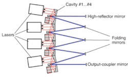
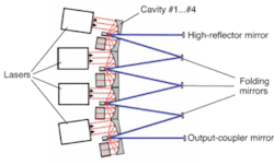
The higher beam quality attainable with the diode-pumped disk laser (as compared to the lamp- and diode-pumped rod laser) is primarily a function of the ability to dissipate heat from the lasing medium. The YAG rod (roughly 6 mm in diameter and 150 mm in length) is cooled by water that circulates past the outer diameter of the rod, resulting in a relatively cool outer skin and a relatively hot inner core, with a maximum temperature at the centerline of the rod. This temperature differential causes thermal gradients and distortion of the rod, and limits the beam quality of rod-style YAG lasers. By comparison, the disk (roughly 14 mm in diameter and 0.2 mm thick) is mounted to a water-cooled block (heat sink), which also doubles as a resonator mirror. Because the disk’s face is mounted to the block and the disk is very thin-a high surface-area-to-lasing-medium volume ratio-the cooling is extremely efficient and results in a nearly negligible thermal gradient. And, as is the case with rod-laser cavities, disk cavities can be coupled in series to increase output power (see Fig. 1).
In addition to its much better beam quality, the disk laser yields another important benefit compared to diode-pumped rod lasers: disk lasers allow longer fiber lengths for beam delivery. Though the full explanation and underlying physics are complicated, a few simple statements can be made. First, back reflection (either from the workpiece or the end of the fiber) gets transmitted back into the laser resonator. This back reflection can result in pumping of the lasing material (rod or disk), and the amount of pumping is dependent upon the volume of the YAG material. The volume of lasing material in one ytterbium:YAG (Yb:YAG) disk (roughly 12 mm3) is very much less than the volume of lasing material in one Nd:YAG rod (roughly 4240 mm3). Back-reflection pumping of the rod can result in extremely high peak powers that can damage internal optics and the fiberoptic cable. The amount of back reflection is a function of fiber length, fiber core diameter, and laser power (longer fibers, smaller fiber cores, and higher powers have the potential to produce more back reflection). With the disk laser, because of its small YAG volume, the back-reflected energy produces only negligible lasing, so fiber lengths are not limited by this phenomenon.
One final advantage of the disk laser (and the diode-pumped rod laser as well) that is worth noting is that the disk is pumped with light energy from diodes. This is in stark contrast to the lamp-pumped laser, which, as the phrase indicates, is pumped via arc lamps. The difference here is that diodes produce a very narrow wavelength range of light energy (almost all of which is used for lasing), whereas the lamps produce a very broad wavelength range of light energy, much of which is unusable for lasing and results in wasted heat energy. This is the basic reason that the disk laser has a wall-plug efficiency greater than 15%, compared to 3% to 4% typical in lamp-pumped lasers (and compared to about 10% for diode-pumped rod lasers).
Advantages of beam quality
The advantage of superior beam quality becomes striking when seen in the context of beam focusing ability and power density of the laser at the workpiece. However, the beam must first be focused into the fiber, and beam quality is the most important factor in defining the size of the fiber that the beam can be transmitted through. Beam quality, sometimes referred to as “beam parameter product,” or BPP, is the product of beam radius and half-angle divergence, expressed in millimeter-milliradians. For a beam focusing into a fiber, the beam radius component of the beam quality is the radius of the focused beam at the fiber entrance, and the half-angle divergence is the equal to the incoupling half angle (see Fig. 2). To have a robust production laser setup, the focused spot size at the input to the optical fiber must be smaller than the fiber core diameter, and small enough to allow for plug-and-play fiber exchange (the ability to replace fiberoptic cables in the field without any service adjustments).
The diameter of the fiber core (φc) is directly related to the focused spot (d) at the workpiece, and thereby the power density as well, by the following equation:
d = φc (f/fc)
Here, f is the focal length of the focus optic and fc is the focal length of the collimating optic.
Therefore, the smaller the fiber core diameter, the smaller the focused spot size. However, the ability to focus to a small spot is not enough. Power is also required, and is quantified using the concept of power density. Power density (Pd) is the ratio of laser power (P) per focused spot area (where area = πd2/4):
Pd = 4P/πd2
So when comparing the diode-pumped disk laser (Trumpf model HLD 4002, 4 kW at workpiece, 200-µm core-diameter fiber) to the lamp-pumped rod laser (Trumpf model HL 4006, 4 kW at workpiece, 600-µm core-diameter fiber) in terms of both spot size and power density, the advantages of beam quality can be clearly seen by the resulting power density or focal length (see Table 1).
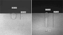
The higher power density can be used to create a high-speed, relatively narrow weld or by using a longer focal length, the lower-speed, wider weld can be created using a much longer focal length (see Fig. 3). The longer focal length is very beneficial because it keeps the processing optics farther away from weld smoke and spatter, and produces a much larger depth of focus (or bigger process window) compared to a shorter focal length.
For welding applications, the most meaningful depth-of-focus relationship is the so-called 5% definition. The 5% depth of focus (L5%) is defined as the full range in which the spot size changes no more than 5%. In other words, if the “in focus” spot size is 0.1 mm, the spot size is no larger than 0.105 mm in the associated 5% depth of focus. The L5% figure is dependent on focused spot size (d), the exit beam quality (BQexit) and the laser wavelength (λ, or 1064 nm for lamp-pumped YAGs and 1030 nm for diode-pumped disk lasers), as seen in the following equation:
L5% = d2/(6λBQexit)
Thus, the beam quality of any laser directly defines its ability to focus and the associated parameters of spot size, focal length, and depth of focus (see Table 2).
Remote welding
For several years in the CO2 laser world, a unique concept of welding parts has been evolving. The process, now well known as remote welding, was possible only because of the increased laser power with an accompanying excellent beam quality (for example, the Trumpf TLF 6000 HQ, 6-kW laser with a near-Gaussian mode). Because of the good beam quality of the disk laser, remote welding has been realized in the YAG world.
Unlike the gantry-style systems with flying optics used in CO2 remote welding, YAG remote welding takes advantage of the fiberoptic beam-delivery capability, coupled to a scanning head on a robot. There are many points of contrast and comparison between CO2 and YAG remote welding. These points should be considered in the evaluation of any remote welding system. They also represent a context for further study and analysis.
The increased beam quality of the disk laser allows the beam to be transmitted via smaller-diameter fiberoptic cables, thus resulting in either smaller process focus spot diameters at a given focal length (higher power densities for faster processing), or longer process focal lengths for a given focus spot size (larger process window, greater robustness and remote welding capability).
David Havrilla is a product manager for YAG lasers at Trumpf, 47711 Clipper St., Plymouth, MI 48170; email: [email protected]; www.trumpf.com.


