Curious by nature, humans search for ever more detail in what they examine-spurring, for example, the invention of microscopes. But even the highest-quality microscopes bump up against the diffraction limit, which is a function of the light’s wavelength (λ) and the numerical aperture (NA) of the instrument.
In practice, points in the image plane spaced about λ/2 apart can just be resolved. To increase resolution, microscopy can use immersion optics to increase the NA, and go to shorter wavelengths as well-for example, in semiconductor photolithography, which is pursuing both these approaches.
But will the race go on into the x-ray region?
Light sources such as x-ray tubes and synchrotrons are available; x-ray lasers are under development. The problem is with the optics. Refractive optics as used for visible and UV light seem, at first glance, not useful at x-ray wavelengths because of the small x-ray refractive index, which for materials at hard-x-ray wavelengths is only slightly greater than 1 (on the order of 1 + 10-5) To realize x-ray refraction comparable to that achieved by lenses in the visible, a multitude of lenses must be lined up. The absorption path becomes long, however, resulting in beam attenuation.
Alternatively, reflective optics can be used that take advantage of grazing-incidence total reflection or multilayer constructive reflection. Both are severely limited in their capability of aberration-free magnifying imaging and sharp focusing. Fresnel zone plates, based on diffraction, are capable of focusing low-energy x-rays. At multikiloelectron-volt photon energies (of special interest in biology, semiconductor technology, and material science), it becomes increasingly difficult to provide background-free focusing and imaging.
To bypass these problems, researchers are investigating the waveguiding of x-rays by narrow channels. At a waveguide exit, the radiation is expected to be well confined so that a sample can be scanned-for monitoring transmission or fluorescence for topographical or chemical analysis, for example. The smaller the exit, the higher the spatial resolution should be. But how far does such a strategy hold?
Plastic-filled channels
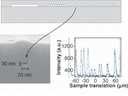
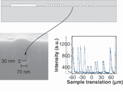
Researchers at the Institut für Röntgenphysik at the Universität Göttingen (Göttingen, Germany) have advanced the waveguide concept.1 Using electron-beam lithography on polymethyl methacrylate (PMMA) spin-coated onto a silicon (100) wafer, they fabricated PMMA-filled channels in silicon of 30 × 70-nm cross section and 4-mm length (see Fig. 1). The device was irradiated head-on by an x-ray beam supplied by the synchrotron at the European Synchrotron Radiation Facility (Grenoble, France) via a monochromator. The passband was set to 12.5 keV and a beam-concentrating two-mirror optical assembly of the Kirkpatrick-Baez (KB) type was used. The KB mirror system increased the flux density by about five orders of magnitude; however, the spot size of 2.5 × 3.8 µm overilluminated the channel entrance considerably so that additional lead shielding became necessary to prevent incoming radiation from bypassing the channel. Careful aligning was necessary.
Finally, the authors achieved proper beam transmission through the channels, counting up to 3.5 × 10⁶ photons/s behind one channel. This corresponded to 4.7% transmission, so that the net flux density gain of the combined KB and channel system amounted to about 4000. The radiation exited with a cross section of 25 × 47 nm (full width at half maximum) into a cone of about 3 mrad. Such a beam can be used for scanning a sample at about a 50-nm spatial resolution-still considerably larger than the x-ray wavelength of 0.124 nm (10 keV).
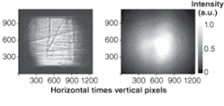
The beam quality at the exit was considerably improved compared to that at the entrance-in particular, the coherence properties (Fig. 2). Whereas at the entrance, behind the KB mirror system, the beam profile is irregular and patterned by interference, it is almost smooth behind the channel exit. The authors modeled radiation propagation in the channel and found good agreement of the beam shape with the experiment, showing that the beam consists of a few channel modes only. This qualifies the device as a highly spatially coherent quasi-point x-ray source, especially useful for holography of biological objects. X-rayed objects could be reconstructed numerically from the recorded far-field diffraction pattern at a resolution given by the waveguide dimensions.
Further channel narrowing may be possible. Recent calculations, however, led to the conclusion that there exists a lower spot-size limit of about 10 nm for any x-ray waveguiding optics.2 On the other hand, others proposed adiabatic focusing by a series of lenses, expecting 2‑nm spot size.3 “Whether x-ray focusing is fundamentally or technologically limited by length scales larger than the wavelength is still under debate, but there may be room for some surprises,” says Tim Salditt, head of the Göttingen group.
REFERENCES
1. A. Jarre et al., Phys. Rev. Lett.94, 074801 (2005).
2. C. Bergemann et al., Phys. Rev. Lett.91, 204801 (2003).
3. C. G. Schroer and B. Lengeler, Phys. Rev. Lett.94, 054802 (2005).


