PC-based digitizers empower modern optical spectroscopy

Modern optical spectroscopy experiments require intensive use of high-powered computers to collect, analyze, store, and display data. Usually the most demanding data-creation component is the high-speed digitizer, which transforms a raw analog voltage signal from an optical detector into a digitized waveform. Commercially available PC-based digitizers provide a low-cost, compact, elegant, and integrated solution for optical spectroscopy.
The fundamental advantage of PC-based digitizers is an unmatched data-transfer rate based on PCI bus-mastering, in which data are transferred directly from the digitizer memory to PC-RAM with no CPU involvement. Personal computer-based digitizers are capable of data-transfer rates in excess of 200 MByte/s. High data-transfer rates enable spectroscopy systems to follow the high signal repetition rates encountered in many optical-spectroscopy applications without encountering trigger losses.
The two most important digitizer attributes in optical spectroscopy are high sampling speed, which improves timing-measurement accuracy, and high vertical resolution, which improves sensitivity to high-dynamic-range signals. High sampling speed and high resolution are opposing digitizer features. Roughly speaking, a higher-resolution measurement takes longer to perform and therefore is limited to a lower sampling speed. Therefore, the design of an optical-spectroscopy system requires an optimal choice between high resolution and high sampling speed for a particular application.
Lidar spectroscopy
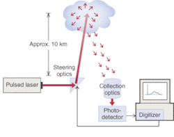
Laser radar, or lidar, although used in such diverse fields as surveying forest growth and vehicle speed policing, finds one of its principal uses in atmospheric science (see Fig. 1). Different lidar systems can be optimized for meteorology, wind-speed measurement, monitoring climatic changes, ozone monitoring, and pollution monitoring. Simple lidar systems use a single optical frequency. More-sophisticated systems involve dual laser frequencies for species identification or measuring optical Doppler frequency shifts to obtain scatterer velocities.
Pulsed lidar uses a high-power pulsed laser with typical pulse durations on the order of 10-ns duration, wavelengths on the order of 500 nm and laser repetition frequencies of 50 to 100 Hz. The pulse is often directed into the atmosphere through steering mirrors. Atmospheric constituents-which could be specific molecules, suspended particles, water vapor, or droplets-scatter the pulse in all directions. Studies are usually confined to within the troposphere, the dense layer where most weather occurs, which is below a 15-km altitude. A very small fraction of the atmospherically scattered light is gathered by collection optics and then directed toward a photodetector, the voltage output of which is sent to a digitizer.
When the incident laser beam is aimed in a given direction, the laser pulse triggers the digitizer. The light signal intensity, as a function of time, t, indicates the light intensity scattered from a given altitude x, where x = ct/2.
Because the speed of light, c, can be expressed as 300 m/µs, the maximum 30-km roundtrip to the top of the troposphere gives a maximum laser-pulse time-of-flight of (30 km)/(300 m/µs) = 100 ms. Typically, lidar systems require a sampling rate on the order of 100 million samples (MS)/s, which leads to a spatial resolution on the order of 1/2 x (300 M/µs)/(100 MS/s)=1.5m.
If the atmospheric light scattering were uniform with altitude, the light intensity detected on the ground would drop inversely as the square of the altitude. This rapid decline leads to a detected light signal that drops over several orders of magnitude with time. The high-dynamic-range lidar signal, therefore, requires the highest available digitizer resolution: 14 bits at 100 MS/s.
Sometimes different detectors are used to cover different ranges of lidar signal intensity. In one novel dual-detector technique, a photodiode detector provided the high-intensity, low-altitude early parts of the signal, creating an output voltage proportional to the instantaneous incident light intensity. For later high-altitude, low-intensity parts of the signal, a photomultiplier tube (PMT) was used. Because of the high electrical gain of the PMT, it could be configured to provide electrical pulses upon detection of a single light photon. The outputs of each detector were connected to the two channels of a digitizer equipped with two independent analog-to-digital converters (ADCs) driven by the same high-speed sampling clock signal to provide simultaneous sampling on both channels. Thus, the customer could use the early-time continuous detector and the late-time shot-event PMT detector with absolute confidence in the time alignment of the two detector signals.
Scanning the laser-beam angle enables the lidar system to image the atmosphere, and the lidar signal is often averaged at one specific laser angle to improve signal-to-noise ratio (S/N). Fast repetitive capture is paramount to provide the fastest overall lidar scan speed. The required capture time of 100 µs at a sampling rate of 100 MS/s gives a waveform size of 10,000 points. Modern PC-based digitizers with ultrafast PCI transfer speeds are able to capture 10,000-point waveforms at rates in excess of 1000 waveforms/s. As a result, lidar systems are limited only by the 100-Hz laser trigger rate and not by the digitizer data transfer rate.
Cavity ring-down spectroscopy
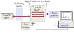
Laser cavity ring-down spectroscopy (CRDS) is a powerful technique that has emerged over the past 25 years with the availability of high-reflectance mirrors (see Fig. 2).
A high-power light pulse from a tunable laser is directed through matching optics and along the central axis of a laser cavity with high-reflectance mirrors (greater than 99.9%) at either end. The light pulse bounces back and forth between the two mirrors, losing intensity with each reflection and decaying exponentially. The light leaking from the cavity is monitored throughout by a photodetector at one end. The exponential decay constant of the empty cavity is reduced upon introduction of an unknown gas sample into the cavity, which provides molecular absorption as an alternate light-loss mechanism. Measuring the change in the cavity-decay time constant as the laser light frequency is swept enables sensitive molecular-absorption spectroscopy measurements and detection of trace amounts of gas. Because it measures only leakage decay times, pulsed CRDS is intrinsically insensitive to fluctuations in laser intensity.
The measurement of time constants from exponential decays of any kind requires the highest available digitizer resolution for following the long exponential tail. The relative error on the time constant is roughly equal to the decay S/N. Because decay times are typically on the order of several milliseconds, a sampling rate on the order of 100 MS/s is sufficient. At this sampling rate, digitizers with 14 bits of resolution with intrinsic S/Ns in excess of 60 dB are available, allowing measurement of time constants to accuracies of 0.1% or better.
Fast repetitive signal capture enables repetitive signal averaging and further improvement of time-constant measurement precision. As with lidar, high-speed PC-based digitizers allow rapid data transfer such that data collection is limited only by laser repetition rate, on the order of 100 to 200 Hz.
Laser ultrasonics
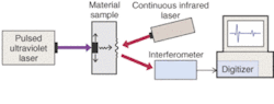
Traditionally, ultrasonic inspection (a noncontact technique that allows the generation and detection of ultrasound within a sample using laser light alone) requires direct contact between an ultrasonic transducer and the material under test; or at least indirect contact through a medium such as water (see Fig. 3).
A high-power UV laser pulse of about 10-ns duration targets one side of a sample. The resultant sudden thermal expansion creates an ultrasonic pulse, which travels through the sample and impinges upon the other side, creating surface undulations. A second IR laser beam is reflected off of this undulating surface and into an interferometer, where it is combined with a reference beam. The voltage output signal of the interferometer furnishes an ultrasonic displacement signal from the surface.
Scanning-laser ultrasonic systems are used as a noncontact method of default detection within large structures such as aircraft fuselages. Because of its wide ultrasonic frequency-excitation band of 100 MHz or more, however, laser ultrasonics is also a powerful method of material evaluation. With increasing ultrasonic frequency, the attenuation increases as wavelength decreases below the size of microstructural crystalline grains. Ultrasound at 100-MHz frequency has a wavelength of tens of microns, which is comparable with the size of crystalline grains within a metal. Consequently, by studying the frequency dependence of ultrasonic attenuation, laser ultrasonic spectroscopy can follow the microstructural evolution of metals during various treatments.
To follow ultrasonic frequencies as high as 100-MHz and higher, laser ultrasonic systems usually require the highest available digitizer sampling rates (1 GS/s or more). While high resolution is desired, the high sampling-rate requirements usually limit digitizer resolution to 8 bits. Fast repetitive signal acquisition is desired for signal averaging, fast scanning, or to follow fast material processing treatments. As in the other spectroscopy applications, high-performance PC-based digitizers offer repetition rates limited solely by the laser pulse rate. ❏
ANDREW DAWSON, formerly an applications engineer responsible for ultrasonic applications, is worldwide sales manager at Gage Applied Technologies, 1 Provost, Suite 200, Lachine, QC H8S 4H2, Canada; e-mail: [email protected].