POWER SUPPLIES: Performance factors characterize high-power laser-diode drivers
GENE KUNTZ
The need to drive progressively higher-power diode-pumped solid-state lasers, laser-diode bars, and laser-diode stacks has driven system developers to seek quality laser-diode power sources with output currents ranging from 10 to more than 100 A for many applications. Several factors must be considered, however, in selecting the appropriate high-power laser-diode driver for any given application.
Voltage versus current
Laser diodes are inherently current-driven devices with varying load impedances depending on the drive current. Despite this fact, they are often driven with bench-top voltage-output power supplies. Voltage sources, typified by most bench-top power supplies, are designed to carefully ramp up voltage at turn-on, leaving the current to adjust to the load requirements. The operating point of most laser diodes, however, is characterized by low differential impedance (dV/dI) so small changes in voltage cause large changes in drive current. Hence, the use of a voltage source generally results in poor power stability and increases the risk of overdriving current to the diode. Consequently, the user must slowly ramp up the power supply voltage to avoid current spikes that might damage the device.
A current source, by contrast, holds current steady while adjusting output voltage to compensate for changes in load impedance, which allows power control over a wide range of impedances and provides relatively high stability, ease of use, and safety in driving laser diodes.
The expense of high-power laser diodes also makes device protection a key consideration in selecting current sources for testing, characterizing, or qualifying devices. Device protection concerns generally fall into three areas: transient protection, output limit control, and temperature monitoring.
Transient protection
To avoid electro-static discharge (ESD) a laser-diode driver must hold the output connections at the same electrical potential when the current source is off to minimize the possibility of ESD damage when the device is connected to the instrument. A normally closed relay on the output leads achieves this by shorting the device leads together when the instrument is turned off.
The source should further protect a device by ensuring it does not induce transients when the output is applied to the device. A current source should slowly ramp the output current to the desired level, thus avoiding transients when power is applied to the device. An overdamped turn-on response can limit the effects of turn-on transients and should not be confused with features that comply with the CDRH (Center for Devices and Radiological Health) requirement for turn-on delay for personal safety.
In addition, the instrument should provide a means to suppress transients coupled from the AC input power stage. This is usually addressed with appropriate input power filtering.
Power and temperature limits
Sudden changes in circuit impedance result in rapid changes in drive voltage from the current source. So a diode-driver source that allows a user to set current limits just above the selected output current will reduce the chance of accidentally overdriving the device. Instruments generally implement this protection by either shutting off the output or clamping the output to user set limits when either the current or voltage limit is reached.
The ability to monitor a temperature sensor and allow the user to set a temperature limit enables output power to the laser diode to be automatically turned off at the set temperature limit. The instrument should also allow the user to input the appropriate sensor constants for calibration to improve the accuracy of the temperature measurement.
In addition to monitoring the temperature of the device, the instrument should monitor its own internal system temperature. Poor ventilation around the instrument such as blocked airflow can cause excessive heat loads that could overheat internal components, damaging the instrument and affecting output current and measurement accuracy.
The user needs to be particularly careful not to select a supply that provides significantly more power than is actually required for the intended application. Parameters such as output current, set-point accuracy, noise, transient suppression, and current measurement accuracy often scale with the maximum output power. So it is essential to ensure that the selected power supply matches accuracy requirements as well as output power requirements.
Instrument control
The ease of interfacing the current source into an existing test setup can be a critical factor in selecting a driver. Therefore, the operational characteristics of the front panel should provide intuitive controls with enough feedback to allow the user to know exactly how the instrument is configured to ease set up and monitoring of test equipment.
Higher-power lasers also require a heightened awareness of laser safety. Selecting a source with one or more safety interlocks will allow the user to control when the output is enabled based on a variety of situations that can range from personnel safety concerns, such as monitoring when a door is opened, to laser-diode protection concerns like monitoring coolant flow on chillers.
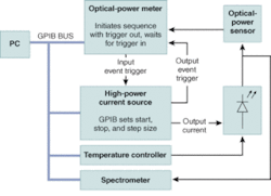
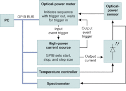
If the test scenario requires remote control of the instrument, a common control interface such as a general-purpose interface bus (GPIB; IEEE 488) is useful. When selecting an instrument, make sure that full functionality is supported through the GPIB interface, including locking out front-panel controls when in remote operation. This will prevent inadvertent changes to the instrument when operating remotely. With system integration it is often necessary to control the laser-diode driver output current relative to another instrument in the system (see figure, p. 123).
QCW and CW modes
The two primary output modes used with high-power laser diodes are continuous-wave (CW) and quasi-continuous wave (QCW). The QCW mode can also be thought of as a pulse mode. A current source that accommodates both operating modes can simplify testing setups as well as save money and valuable rack space.
Even if the application only requires driving CW lasers, pulsed power input to a CW laser package can significantly reduce the amount of heat generated in a device during testing. One typical test application involves characterization of CW devices in a pulsed light-current-voltage (L-I-V) mode. Temperature-sensitive parameters such as output power, wavelength, and threshold current can be compared in pulsed versus CW tests. Large differences between the pulsed and CW L-I-V can gauge the quality of the die attachment or provide early detection of poor laser quality.1, 2, 3
As a word of caution, driving a QCW laser with a CW source can cause catastrophic failure in the device. For this reason the power source should provide an intuitive yet fail-safe approach to allow the user to switch from QCW to CW modes.❏
REFERENCES
1. D. Hodgson, B. Olsen, Protecting Your Laser Diode, ILX Lightwave Application Note 3.
2. D. Hodgson, K. Noonan, B. Olsen, T. Orosz, Pulsing a Laser Diode, ILX Lightwave Application Note 11.
3. S. Bennett, Testing Bond Quality by Measuring Thermal Resistance of Laser Diodes, ILX Lightwave Application Note 13.
GENE KUNTZ is the vice president of product planning and development at ILX Lightwave, 31950 East Frontage Rd., Bozeman, MT 59715; e-mail: [email protected]; www.ilxlightwave.com.