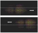
Researchers at Stanford University (Palo Alto, CA) have developed and modeled (though not yet put into practice) a method that slows, stops, or time-reverses light pulses at room temperature using only linear optics and electro-optic modulation.1, 2 Two parallel chains of coupled microcavity resonators in a photonic-crystal structure are coupled side by side; the dispersions of the two chains are controlled to create the desired effect.
Previously, light has been stopped or slowed in so-called Bose-Einstein condensates made of magnetically trapped clouds of atoms cooled to near absolute zero (see Laser Focus World, April 1999, p. 16), in solids (see Laser Focus World, February 2002, p. 36), in cryogenically cooled semiconductor quantum wells (see Laser Focus World, November 2004, p. 21), and in various other materials using electromagnetically induced transparency (EIT). In addition, light pulses have been time-reversed via processes such as four-wave mixing. All these previous techniques, however, are nonlinear and share one or more of the practical disadvantages of complexity, the need for cooling, and narrow spectral bandwidths. The non-EIT-based Stanford technique avoids these problems.
The chains of cavities, called coupled-resonator optical waveguides (CROWs), can be fabricated in common semiconductors such as aluminum gallium arsenide (AlGaAs). In operation, a light pulse is first sent into one of the two CROWs. “As the photon pulse propagates inside the crystal, we shift the relative resonance frequencies of the cavities to transfer photons from the first subsystem of cavities to a second subsystem of cavities,” explains Mehmet Fatih Yanik, one of the researchers. The resonance frequencies are altered by slightly modulating (by a factor of less than 10-4) the refractive index of the structure via Kerr nonlinearity through an external optical pulse or via electro-optic effects.
The modulation is tailored to create the desired outcome. For example, for time reversal, the second subsystem is made to have dispersion properties that are completely the opposite of those in the first subsystem. “As a result of this, the transfer of photons from the first subsystem to the second subsystem completely inverts the spectrum of the light pulse, which generates a time-reversed version of the original pulse,” says Yanik. "The time-reversed pulse -exits the second subsystem after this spectrum-inversion process is complete."
Practical implementation
In a photonic-crystal implementation of the device in AlGaAs, low-index regions can be created by selective oxidation of AlGaAs regions after patterning with a mask, says Yanik. Holes are generated by etching through the photonic-crystal slab. For operation in the 1.5-µm-wavelength region, the feature sizes of the photonic-crystal patterns would range from 100 to 300 nm, with a lattice spacing of around 500 nm. The thickness of the slab would then be around 200 to 400 nm. The design lends itself to monolithic integration on a chip.
"In collaboration with two other -research groups at Stanford, we have plans to fabricate one of our new designs," says Yanik. "This new structure can be used to stop light pulses and also to time-reverse simply by changing the pattern of refractive-index modulation. We are also working on a microwave prototype."
Coupling more than two CROWs together could have advantages for more-complex information-processing purposes, notes Yanik. "Such dynamic photonic-crystal and resonator structures can enable new information processing capabilities that were not possible previously." Two coupled CROW arrays are sufficient for slowing, stopping, and time-reversal, however.
Non-EIT manipulation of light in such a simple, linear fashion may be important to adaptive optics, detection through random media, subwavelength focusing, and fiberoptic communications. For fiberoptics, the device could be used for dispersion compensation, delay lines, and optical buffers.
REFERENCES
1. M. F. Yanik et al., Phys. Rev. Lett. 93 (Dec. 3, 2004).
2. M. F. Yanik and S. Fan, Phys. Rev. Lett. 93 (Oct. 22, 2004).
