Crosstalk challenges CMOS sensor design
HUI TIAN, QUN SUN, JIM LI, and ABIGAIL DOMINE
Crosstalk is normally considered to be problematic in CMOS sensor design. However, if managed properly, crosstalk can be used to the designer’s advantage.
Thanks to two decades of continuous improvement, CMOS image sensors are now “ready for prime time.” Formerly considered to be low quality and suitable only for toys, they are now found in technologically sophisticated applications such as cell phones, security cameras, automotive imaging systems, and digital still cameras. In fact, unit shipments of CMOS image sensors in 2005 will surpass CCDs for the first time, according to In-Stat/MDR.1
Although they offer many benefits compared to CCDs, including lower cost and lower power requirements with higher integration, smaller chip size, and greater simplicity in the design stage, CMOS sensors are not without design challenges.2 One key consideration is crosstalk. It is commonly believed that crosstalk always degrades the spatial resolution, reduces overall sensitivity, causes color-signal mixing and, consequently, leads to image error after color correction. However, instead of focusing on lowering crosstalk, these problems can be addressed at the color-imaging system level. By modifying the spectral sensitivities of color filters in a CMOS sensor in the presence of crosstalk, it can be demonstrated that the imaging system can still provide color production as good as, if not better, than in a system without crosstalk.
Crosstalk
After several years of buying new products with ever-higher pixel counts in the digital still-camera market, the average consumer equates the number of “megapixels” with image quality. Shrinking sensor pixel size, however, poses significant challenges to sensor design. As pixel size gets smaller, the well capacity shrinks, resulting in less dynamic range. The photon collection area also shrinks, causing less sensitivity. Noise, coupling, and nonuniformity become more severe and visible. The pixel crosstalk also inevitably gets higher.
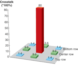
Crosstalk occurs when photons falling on one pixel are “falsely” sensed by other pixels around it. For example, we call it crosstalk if we shine highly focused light only on a red pixel, and the blue pixel shows a response (see Fig. 1). In this extreme case, the blue channel response will be too high and skew the real pixel color. Reducing crosstalk in small pixels has thus become one of the most difficult and time-consuming tasks in sensor design.
Controlling crosstalk
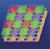
Several components contribute to crosstalk in a sensor. Each can be reduced with careful design and process optimization. For example, the color filter and microlens of a CMOS sensor can contribute to crosstalk (see Fig. 2). In a modern CMOS image sensor, building a microlens is standard-almost all foundries routinely build them with very good reliability and yield. Good control of stack height allows a larger acceptance angle and an aggressive f number. As the pixels go from the center to the edge of an array, they see more and more tilted chief rays from the main imaging lens. To accommodate the tilted chief ray, the microlens must be gradually shifted off the pixel center as the microlens goes from the array’s center toward its edge. This microlens shift, together with the wide incident light angle, creates a large amount of crosstalk. To minimize this crosstalk, optical simulation can be used to carefully design the microlens array with a limited shift amount. The dielectric structures that utilize the internal reflection at the dielectric-film and air-gap interface have been developed to concentrate the incident light in the selected pixel.3 The emerging gapless microlens technology can also help suppress the crosstalk.Optical crosstalk can also occur when incident light bounces around inside the chip. A common technique to mitigate this problem is to use a top metal shield between pixels to minimize the light that goes into the wrong pixel. This technique has to be carefully designed to avoid having a negative effect on sensitivity.
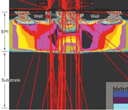
Electrical crosstalk inside silicon can also be very significant. In a CMOS sensor, the epitaxial layer (EPI) between the well and the substrate of the p-type layer forms a free-flowing channel for photoelectrons (see Fig. 3). Because most of the blue photons will be absorbed near the silicon surface, this effect is more severe for longer-wavelength photons. Ways to suppress this electrical crosstalk include shrinking EPI thickness, inserting diffusion barriers, and implanting a deep p-type impurity to isolate the substrate.Compensating for crosstalk
Even when everything is done correctly, there will still be some level of crosstalk, just like other unwanted signals. So a natural question is: how much crosstalk can the application tolerate? To answer this question we have to resort to a camera system performance evaluation. One commonly used metric is color reproduction quality. After all, it is the color reproduction quality, not crosstalk itself, that is the end users’ real concern.
Colorimetrically, the accuracy of color reproduction is based on how closely the spectral responses of the image sensor match the human vision responses. Mathematically, this can be described as how close the spectral responses of the image sensor match the color-matching functions or their linear combinations (when noise is not involved).4 So the design goal should be to optimize the spectral responses of the whole image sensor system to achieve the best color reproduction. In this approach, the color filters can be optimized to compensate for the effects of crosstalk.
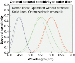
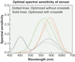
This design method incorporates a physical-sensor spectral-response model that is based on silicon parameters. The first step is to study the components that affect the spectral response of the CMOS image sensor, including microlens, color filter, sensor quantum efficiency (QE), and spectral response shift caused by crosstalk inside the sensor. This is performed using a complex commercial tool. Based on the results, a super-linear crosstalk function is then constructed, which feeds into a system simulation model. The accuracy of modeling was verified using a real image sensor and a real experimental measurement. For simplicity, a smooth cubic-spline function model with controllable peak positions and widths is applied to simulate the spectral sensitivity of color filters. The peaks and widths are optimized based on the µ-factor for different crosstalk levels.4 The µ-factor is a quality metric for the evaluation of a multispectral system with an arbitrary number of color channels. A graphical representation of simulation results compares the spectral sensitivity of two filter sets-one optimized in a crosstalk-free condition, the other set optimized under a crosstalk condition (see Fig. 4). Contrary to common sense, compared to the color filters in the crosstalk-free condition, the optimized color filters under crosstalk should have larger overlaps among color channels to compensate for the effect of crosstalk. The peaks of spectral sensitivity of color filters also must be slightly modified.With the color-filter sets optimized (either with or without crosstalk), the spectral sensitivity of the whole image system can then be considered. We found that the set of color filters that were optimized for crosstalk conditions provided the better overall color reproduction. We also found that the optimized color filters under crosstalk provide the same quality, if not better, as the optimized color filters without crosstalk under the crosstalk-free assumption. In addition, lowering overlaps among spectral responses of color filters does not lead to optimal color reproduction under crosstalk.
The key in sensor design is to correctly characterize or model the crosstalk and build optimal color filters to compensate for its effects. This is a sensor design approach driven by the color-reproduction point of view. Of course there are many practical constraints that prevent manufacturers from achieving the desired optimal results. In practice, the whole design approach should also consider the effect of noise.Surprisingly, crosstalk is not necessarily an enemy for the CMOS sensor designer. By engineering the shape and amount of crosstalk, one can expect to achieve better image quality at the system level and can look forward to future improvements as CMOS sensor technology matures. “Managing crosstalk, along with uniformity and sensitivity, will help CMOS image sensors improve image quality at a lower price for consumers,” says Ben Wu, chairman and cofounder of IC Media.
REFERENCES
1. www.instat.com/press.asp?ID=1107&sku=IN0401157MI, In-Stat/MDR (2004)
2. E.R. Fossum, IEEE Transactions on Electron Devices 44(10) 1689 (1997).
3. T.H. Hsu et al., IEEE Electron Device Lett. 25(6) 375 (2004).
4. P. L. Vora and H. J. Trussel, J. Opt. Soc. Am. A 10, 1499 (1993).
HUI TIAN is principal sensor scientist, QUN SUN is color imaging scientist, JIM LI is chief technology officer and cofounder, and ABIGAIL DOMINE is director of marketing at IC Media, 5201 Great America Pkwy, Suite 422, Santa Clara, CA 95054; e-mail: [email protected].
