Automated optimization advances software for illumination design
Light-emitting diodes (LEDs) have longer lifetime, draw less power, and are more rugged than incandescent bulbs. These attributes make the LED a particularly attractive light source for flashlights intended for rough environments, such as police, fire, and rescue work, the military, and recreational outdoor activities. However, LEDs have lower luminance compared to a similarly sized light bulbs, making it imperative to collect and concentrate as much of the source output as possible. With the help of illumination-design software with an optimization feature that is not yet commercially available, designers were able to create a novel optic for an LED flashlight that meets constraints on package size, light collection efficiency, output luminance distribution, and manufacturing cost.
Design goals
For several years, Emissive Energy (North Kingstown, RI), a manufacturer of high-performance, LED-based lighting equipment, has worked to develop a “next-generation” LED flashlight with superior mechanical, optical, and electrical characteristics. Specifically, the company wanted to produce a compact, rugged, long-lifetime flashlight, and wanted to achieve a total lumen output comparable to incandescent bulb flashlights.
Emissive Energy decided to partner with Optical Research Associates to develop a workable optical design. At the outset, constraints were placed on the design form of the flashlight optics to meet goals for production cost, package size, optical performance, and ruggedness. In addition, Emissive Energy wanted to differentiate its product from competitive LED flashlights and to stimulate demand for a product that would be significantly more expensive than the generic incandescent-bulb flashlight.
Emissive Energy hoped to distinguish its product by using a streamlined look-a straight cylinder, rather than the traditional flashlight with a flared end-and an overall package diameter of one inch or less was required. To minimize production cost, they wanted to rapidly assemble all the optical and mechanical components without optical adjustments, such as focusing.
Design goals for optical performance included high efficiency to maximize battery life and maximum on-axis intensity, or punch, to maximize the illumination of distant objects. Incandescent flashlights typically increase the diameter of the output optic to increase the punch, but Emissive Energy needed the diameter to remain small.
Designers also wanted the projected spot to appear homogeneous and structureless, with no small-scale bright or dark areas. This is particularly important for applications in law enforcement, search and rescue, and the military, to avoid misidentifying or overlooking elements in an illuminated scene. A smooth, structureless output would also differentiate the product from most other flashlights on the market.
Automated optimization
Solving the design problem consisted of two major steps: determining a proper design shape that had the potential to meet all constraints and using a novel software routine to refine the shape for optimum performance.
Traditional flashlights place the source near the focus of a parabolic reflector that collimates the light, but this approach only controls a small portion of the output from a single emitter LED source (see Fig. 1). The LED can be turned toward the reflector, but this configuration blocks part of the output.
A solution that has been used previously with LEDs is to mold the collection optics from a single piece of plastic and to incorporate two separate beam paths. One path is a parabolic reflector, which operates by total internal reflection (TIR), and the second is a refractive system for collimating the light that isn’t intercepted by the reflector. This approach provides high collection efficiency but tends to reimage the source in the projected beam. Because LEDs with high flux and high luminance have a somewhat square shape with spatial structure, the projected beam reproduces that structure.
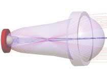
The design approach in this case changed the TIR surface to an ellipsoid, which focuses the light to a blurry spot internally, and then uses a final refractive exit surface to reimage the spot in the far field (see Fig. 2). This homogenizes the light more thoroughly than a parabolic reflector, thus eliminating residual structure created by the source. In addition, the second refractive beam path collects the flux that misses the TIR surface but is designed to avoid creating the square beam pattern found in many other LED flashlight optics. The final output surface is then slightly faceted to further increase beam homogenization without sacrificing performance.
The difficulty with this approach is that the two beam paths overlap substantially, so that the final surface has to do double duty. It has to work with the outputs of the elliptical reflector and with the first refractive surface. Finalizing the design thus required simultaneously optimizing the ellipse, the two refractive surfaces, and the connecting surfaces.
Virtually all design programs for imaging optics include routines that can optimize a multisurface system. However, no commercial illumination-system design software currently offers this capability. One reason for this is that it is more difficult to define a common measure of what constitutes good performance in an illumination system. In contrast, for an imaging system, good performance almost always means minimum spot size. Illumination design also involves nonsequential tracing of Monte Carlo raysets (large number of randomly chosen rays whose distribution replicates the luminance distribution of the source), which makes it difficult to create a robust optimization algorithm.
Use of illumination design software with an optimization feature not yet commercially available ultimately enabled 90% of the emitted energy from the LED flashlight to reach its target. As illumination tasks become more sophisticated and demanding, we believe that this type of optimization capability will be critical in maximizing performance.
William Cassarly is principal engineer at Optical Research Associates, 3280 E. Foothill Blvd., Suite 300, Pasadena, CA 91107: e-mail: [email protected].


