Zoom lens maintains telecentricity
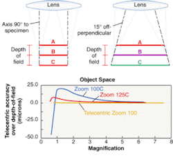

In optical metrology, the positions of distinguishing points within an image are measured to high precision. To maximize measurement accuracy and throughput, a telecentric imaging system is a must. Telecentricity is defined as having the pupil of an optical system at infinity. When the pupil of an optical system is at infinity, the chief (or principal) ray is parallel to the optical axis. A telecentric cone of rays emanating from an object point remains perfectly perpendicular to the object plane across the entire depth of field (see Fig. 1). In contrast, conventional lens cones, which are not perpendicular, produce varying measurements through the depth of focus, causing apparent object size to vary.
With a telecentric imaging system, consistent measurements of a feature can be made regardless of how close to the focal plane the feature might appear—that is, whether it is in the "optimal" focal plane or a few focal ranges out from that plane. The object will blur with defocus, but the centroid of that blur will not change position. The viewer can accurately measure topographically rich objects without having to re-establish focus for every surface and feature. This quality can be a tremendous time saver and throughput booster.
In one example, images of the leads emanating from the center of a probe card are imaged. Telecentric imaging shows consistent alignment of in-focus and out-of-focus portions of the leads, as well as imaging of only the tops—rather than the sidewalls—of leads, and permits accurate positional measurements. Nontelecentric imaging lacks these qualities (see Fig. 2).

In addition to achieving telecentricity, minimizing distortion is also crucial in an optical metrology system. Distortion is defined as a change in magnification with field. Any distortion that results from a conventional lens translates directly into error in measurement in an optical metrology system. In such a system, the position of the same object can be measured with different results depending upon its location in the field of view. Although errors induced by distortion can be calibrated out, such a procedure can be difficult and time-consuming.
The telecentric zoom challenge
Most early optical metrology systems consisted of a fixed-magnification telecentric system for imaging the target object. While optically accurate, these fixed-lens telecentric optics locked the user into a single field of view, limiting viewing flexibility and throughput efficiencies. If an object contained multiple measurement targets outside of the field of view predetermined by the fixed magnification system, the operator would have to navigate a way to the next field of targets, re-establish focus, and painstakingly stitch the images together.
With increased demand for higher measurement productivity, conventional zoom-lens imaging systems were adapted to optical-metrology applications to provide greater versatility and flexibility. Unfortunately, telecentricity is extremely difficult to achieve within a zoom optical system, so these early systems posed significant accuracy problems in depth of focus and perspective.
A typical early zoom system had a pupil that varied with magnification. The stop in the system resided on one of the zooming elements and the pupil's location would change as the magnification changed. Some early zooms had a single telecentric magnification somewhere within its zoom range, but telecentricity across the rest of the zoom range was lost. In addition, the need to keep the optical systems as compact as possible prevented the zooms from being even close to telecentric at low magnification, as telecentric systems require large front optics (the first lens must be larger than the object under measurement).
Two other aspects of zoom systems have been problematic for the metrology industry. Many of the early zoom systems had a fairly large amount of distortion and vignetting inherent in their designs, and the amount of distortion and vignetting varied with magnification. Distortion resulted in different measured values depending upon the location in the field of view, while vignetting lowered the contrast of specimens across the fields.
All of these factors—telecentric accuracy, distortion, and vignetting—must be considered in approaching a telecentric design for metrology that performs consistently across an entire zoom range.
Metrological versatility
A telecentric zoom lens developed by engineers at Thales Optem has been designed to overcome the many hurdles facing broad-range telecentric zooms. The telecentric zoom 100 is a 10:1 telecentric zoom optical system that delivers 0.2° telecentricity, zero vignetting, and 0.1% distortion.
The first identified requirement was that the zoom had to maintain control of the entrance pupil of the system, yet yield a numerical aperture that would increase appropriately with an increase in magnification. In addition, vignetting had to be eliminated and distortion throughout the entire zoom range had to be minimized, if not eliminated.
The design team achieved telecentric zoom by placing a longitudinally fixed aperture in front of any moving elements in the zoom. This aperture location is fixed in position to be imaged at infinity by the lenses in front of it. By placing the aperture before any moving elements, the telecentricity on the object side is ensured regardless of the placement of the lenses behind it. To allow the numerical aperture of the system to increase, the aperture is made to be an iris that is slaved to the movement of the zooming elements. The rate that the iris opens and closes with the change in magnification allows the f number on the camera to be kept constant.
To prevent vignetting, the lenses are kept large enough that the iris is the sole limiting aperture throughout the full zoom range. This results in a greater need to correct aberrations in the system, because vignetting cannot be used to do so. The powers of the different elements are used to contain the rays within a reasonable diameter. It was desired to keep the diameter of the back elements as small as possible and let the front elements define the diameter of the total system. Eliminating vignetting is critical in a telecentric zoom system. If the system encounters vignetting, the chief ray of the system does not correspond with the centroid of an outer bundle of light; telecentricity, in the practical sense, would change wherever the vignetting occurred.
Distortion was controlled by using a large collection of lenses. The first group of collimating lenses behind the zoom groups caused most of the distortion; refining this first group of lenses minimized image distortion to levels consistently below 0.1% throughout the entire zoom range. This amount of distortion represents a subpixel error over the entire 10:1 field of view (see Fig. 3).

Modularity was designed into the system to allow the zoom lenses to be used for as many different types of applications as possible. The nominal design is intended for use with a 1/2-in.-format camera. Although a popular format, such a camera is not the size of the vast majority of cameras now available. Different modules have been designed to go onto the back of the telecentric zoom lens to adapt it to a variety of different format cameras, allowing the same field of view to be projected fully onto different-format cameras.
Different fields of view are achieved through interchangeable front modules. By changing the objective lens, different magnification ranges are allowed. Each objective is designed to maintain the telecentricity of the nominal zoom design. With the range of available objectives, the horizontal field of view ranges from 0.85 to 47.7 mm. Front modules also allow for coaxial illumination and polarizer/analyzer options to be integrated onto the system. The lens is operated either manually or by motors; the electronic version has a motor to operate both the zoom and the iris.
Although metrology is the primary purpose for this lens, we are uncovering other applications for it. The ability of a telecentric optical system to look "straight down" onto its target across the full field of view permits clean viewing of holes. Drilled holes can be seen to their bottoms regardless of their position in the field of view; anything blocking the hole, such as burrs or chips, can be clearly identified. Telecentricity is also useful when inspecting ball-grid arrays. Whereas a conventional optical system looks at the center of the balls in the center of the field of view but more and more at the sides of the balls as their pattern radiates away from optical center, the "vertical axis" of each ball across the grid is clearly apparent under telecentric viewing.
MARK SANSON is an optical engineer at Thales Optem, 78 Schuyler Baldwin Dr., Fairport, NY 14450; e-mail: [email protected].