Birefringence helps analyze optical telecom components
Optical designers are using the properties of birefringence found in uniaxial optical crystals to control light in a wide range of applications. Applications for telecommunication equipment include optical isolators, circulators and optical interleavers. Components and systems can be designed and analyzed with optomechanical software, permitting the designer to simulate complete optical systems including mounting hardware and component placement for packaging. These tools have been available for several years and continue to evolve both in capability and user experience. The recent addition of birefringence modeling to the polarization ray trace is enabling simulation of these various applications.1
Birefringence literally means a medium with two different refractive indices varying as a function of polarization. Many materials exhibit some amount of birefringence either due to the material's composition or caused by external forces. Most optical crystals are inherently birefringent. Optical glasses and plastics can have birefringence induced by mechanical stress. Birefringent liquid crystals may be tuned to a desired polarization state with electric fields.
Unique opportunities to manipulate light arise from the optical behavior of uniaxial birefringent crystals that are not available, or cumbersome, with isotropic materials such as optical glass and plastics. In particular, doubling the beam into ordinary and extraordinary waves can result in two distinct phenomena, spatial separation and polarization separation. Spatially, the light can be merely displaced or offset, or an angular separation can be accomplished, resulting in beam separation that varies with distance. For polarization, uniaxial birefringent crystals split the beam into two orthogonal linear polarization states.
Designers use several birefringent elements in conjunction with other polarizing components such as polarizers, rotators, and compensators, and with more conventional optics such as lenses and mirrors to complete an optical assembly.
Simulation of birefringent components
To model a uniaxial crystal, the simulation requires the ordinary and extraordinary indices of refraction and the orientation of the material's crystal axis. The indices are wavelength dependant and must be specified at each wavelength of interest or interpolated from a set of data or a dispersion formula. Typically the model will also include data for the material's bulk absorption.
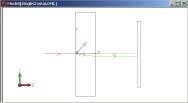
To illustrate the model we trace a ray through a calcite crystal with a thickness of 6.35 mm (see Fig. 1). The refractive indices at a wavelength of 0.6 µm are no = 1.658 and ne = 1.486. Birefringence is often quantified by the difference between these two indices, or
Δn = ne - n0
Calcite has a Δn = -0.172 and is said to have negative birefringence. Materials that have an extraordinary index greater than their ordinary index have positive birefringence.
In this example, the principal section, as defined by the crystal axis and propagation direction, is the y-z plane. The incident ray splits in two at the first interface, with the ordinary ray (o-ray) continuing along the z-axis and extraordinary ray (e-ray) refracting with a negative y component. There is no skew component to the e-ray since it lies in the principal section. As the two rays leave the material, refraction at the second interface causes the rays to become parallel to each other. This occurs because the wave vectors, not shown in the figure, govern the refraction. In fact, the wave vectors after the first interface remain in the z-direction, (0,0,1).
Hence, at the second interface, as they leave the crystal, the wave vectors are normal to the back surface and thus refract parallel to each other. Each ray will experience a different refractive index as it propagates through the crystal. The o-ray sees the ordinary index, 1.658, and obeys Snell's Law. The e-ray's refractive index is calculated using the index ellipsoid, which is a function of the material parameters, no and ne, the crystal orientation, and the wave direction. From the equation for the index ellipsoid,
the e-ray's refractive index n is 1.564955 because the angle q between the crystal axis and the wave vector is 45°.
Polarization-independent isolators
Telecom designers are using these techniques and insights to invent a variety of novel systems that utilize beam and polarization separation offered by uniaxial birefringent materials. Operating in the 1.5-µm region of the spectrum, three birefringent materials that are often used are lithium niobate (LiNbO3), rutile (TiO2), and yttrium vanadate (YVO4).
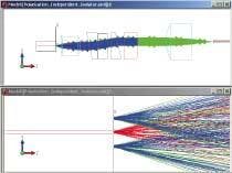
One example that uses the beam separation property is a polarization-independent isolator. This is an optical system that provides isolation as it relays an input optical signal to an output port such as an optical fiber. The isolation prevents back reflections returned from the output port from reentering the input port, as can be illustrated in a design using LiNbO3 crystals (see Fig. 2). The polarization-independent isolator is placed between a semiconductor optical amplifier (SOA) and an output fiber. The input light starts at the origin and travels in the positive z direction. The optical train, from left to right, comprises a collimating lens, a birefringent input wedge, a Faraday rotator, a birefringent output wedge, a birefringent compensator (to make the optical path lengths equal), and a fiber coupling lens. Reflections from the optical fiber at the extreme right of the top portion of Fig. 2 travel back through the system. The bottom portion of Fig. 2 shows the input port in detail. The back reflections are spatially offset from the input port.
These devices provide optical isolation that is independent of input polarization. They are often used as "in-line" isolators for applications involving optical amplifiers. In such cases, an in-line isolator is used on each side of the optical amplifier.
Other applications
Uniaxial birefringent materials play many roles in optical systems both in and out of telecom. Optical circulators and interleavers are common components used in telecommunications systems. Nonimaging applications include brightness enhancers in illumination systems. Novel uses of complex geometries take advantage of such phenomena as total internal reflection and diffuse scattering in conjunction with birefringence to yield innovative solutions to modern-day problems. Armed with modern analysis software and imagination, today's designers have a broad design space for new inventions.
REFERENCES
- R. A. Hassler, G. G. Gregory, E. R. Freniere, Proc. SPIE 4769 (July 2002).
G. GROOT GREGORY is vice president, EDWARD R. FRENIERE is president, and RICHARD A. HASSLER is manager of engineering services at Lambda Research, 80 Taylor St., P. O. Box 1400, Littleton, MA 01460; e-mail: [email protected].


