Chalcogenide glass 'molds' thermal imaging
by Xianghua Zhang
Thermal imaging was once the sole domain of the military because of the high cost of the hardware, mostly the detector. Although the development of small formats (160 x 120 pixel arrays) and amorphous silicon microbolometers in recent years has greatly decreased detector cost, another important component of a thermal camera has not evolved significantlythe optic. It is still made of expensive single-crystal germanium (Ge). Aspheric lenses used in thermal imaging are typically made using the costly single-point diamond-turning process. It is unlikely that the cost of Ge lenses can be dramatically decreased to meet the price target for applications such as night vision for cars.
Zinc selenide (ZnSe) can also be used for some thermal imaging applications, but it suffers from the same problems as Ge. One potential solution to this problem is the use of chalcogenide glass as a material and using a molding process to generate the spherical and aspheric surfaces of the optic.
Making chalcogenide from its elements
Standard chalcogenide glass compositions are of germanium arsenic selenium (Ge22As20Se58, or GASIR1) and germanium antimony selenium (Ge20Sb15Se65, or GASIR2). The raw materials for producing these two glasses are high-purity elementary germanium, arsenic (antimony for GASIR2), and selenium. The fabrication techniques use sealed silica ampoules and rocking furnaces to ensure a good homogenization of glass ingots (see Fig. 1). The raw materials are heated up slowly to a temperature between 750°C to 800°C depending on the glass composition. The homogenization takes between 4 to 5 hours.
After the annealing at 300°C over 20 hours, the homogeneity of the entire ingot is checked by strioscopy, a technique in which light for visualization is diffused by defects in the glass such as striae, bubbles, or inclusions. This check is performed at short wavelengths (0.8 to about 1 μm) and is a rather severe test because these two glasses are mainly designed for applications in the long-wavelength region of 8 to 14 μm. The process ensures a very good reproducibility of glass. The batch-to-batch variation of refractive index is less than 1.5 x 10⁻⁴, which is comparable to the precision of the measurement.
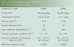
Standard ingot size is 150 mm in diameter and 60 to 70 mm in thickness, from which other diameters can be cored. Unlike germanium, the optical properties of these glasses are not affected by temperature. They can be used up to 200°C, above which there is a risk of deformation for the lenses. The transmission domain largely covers the two commonly used atmospheric windows of 3 to 5 μm and 8 to 12 μm for thermal imaging (see table).
Molding reduces cost
The big difference between GASIR glasses and the commonly used germanium and ZnSe materials is that the former are vitreous materials and the latter are crystalline materials. These two states of solid materials have very different behavior when heated up. Crystalline materials behave like ice, going directly from solid to liquid state at the melting point. No molding is possible. The GASIR glasses behave like plastic: when heated up, their viscosity progressively decreases. At certain temperatures, the viscosity is ideal for the glass to duplicate precisely the surface of a mold. Molding is, of course, much cheaper than mechanical turning.
One of the main disadvantages of GASIR glasses compared to germanium is the relatively high chromatic dispersion (variation of refractive index as a function of wavelength). For thermal imaging, more complex lens designs are generally necessary when GASIR glasses are used. Molding is probably the only cost-effective way to produce aspheric and diffractive lenses from these glasses, although even conventional diamond-turning technology can be used.
Aspheric and diffractive surfaces
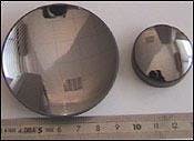
This original, high-precision molding technology has been developed specifically for the production of low-cost and high-performance chalcogenide glass lenses. With this molding process, spherical, aspheric, and aspheric-diffractive lenses can achieve very accurate surface precision (see Fig. 2). The form defects of the molded surface can be less than 0.5 μm. Aspheric and diffractive surfaces enable the reduction of the number of lenses in an optic and an increase in performance of the system. Molded spherical and aspheric-diffractive lenses made with this fabrication process are ideal for applications in which the cost of the optic is a critical feature. This situation is especially common with thermal cameras using uncooled detectors.
The development of high-performance, thorium-free antireflection coatings has resulted in average transmissions as high as 98% over a wavelength range of 7.7 to 11 μm and 95% average transmission between 11 and 12 μm. Thorium is eliminated in the coating because of its radioactivity. These high-efficiency antireflection coatings pass the "cheesecloth" abrasion test.
If a GASIR lens is used as a front element in a lens assembly, then a durable coating is necessary on the external surface. The transmission for a coating designed for this application is currently 90% average from 7.7 to 11 μm, with 95% expected as coatings are further developed. This type of coating has passed severe abrasion tests, complying with the environmental MIL-C_48497_A specifications in terms of adhesion, humidity, and abrasion resistance tests. For example, a two-element optic with a total focal length of 60 mm, an angular acceptance of F/1.1, and a field of view of 15° x 11.5° can achieve an overall transmission of 92%.
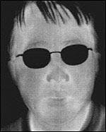
This set of optics has been used with a 320 x 240-pixel-format uncooled microbolometer and appropriate electronics to create a thermal camera with a noise-equivalent temperature difference of 100 mK. This performance is the same as that of an optic made of aspheric germanium lenses (see Fig. 3).
The state-of-the-art process for molding GASIR lenses produces excellent-quality spherical and aspheric lenses. Diffractive lenses are slightly more complicated to produce, but are good enough for most applications. Although the technology does not lend itself to high-volume productionas in, for example, automotive applicationsits yield is still an improvement over pre-existing technology, enabling the production of up to thousands of lenses per batch.
ACKNOWLEDGMENT
The author wishes to express appreciation to DGA/DSP/STTC of French Ministry of Defense for their constant support. Many thanks to my colleagues Yann Guimond and Yann Bellec, the principal contributors to this work.
XIANGHUA ZHANG is chief technology officer of Umicore IR Glass, s.a., ZA du Boulais, F035690 Acigne, France; e-mail: [email protected].


