Manufacturing for OE components opens up
by Armando Valim
Test-gear manufacturers are improving yield by using open software and hardware architectures that combine several crucial disciplines.
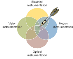
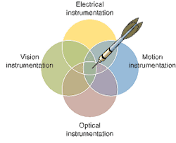
Whether preparing for the future demand or lowering costs today, successful automation of optoelectronic components production is a combination of four unique disciplines: motion, vision, optical, and electrical instrumentation under common software control (see Fig. 1). This modular approach, based upon open standards such as PXI (PCI Extensions for Instrumentation) and CompactPCI, is flexible and scalable, adapting to a range of applications using tightly integrated subsystems to improve time to market, yields, and production costs.
Optical components such as laser diodes and optical microelectromechanical systems (MEMS) cannot be tested using modular optical instrumentation alone because measurements such as optical-power and optical-spectrum analysis are only part of the problem. Electrical signals, nanopositioning, and machine vision are examples of critical instrumentation needed to successfully manufacture and test optoelectronic components. Therefore, the foundation for flexible automation is tight integration of motion, vision, optical, and electrical instrumentation in a computer-based platform. Engineers require subsystems that scale from the R&D lab to the production floor. Early planning for production using reliable, modular instrumentation reduces product development time.
Many systems use open industry standards to achieve flexible automation that enables fast technology changes and continuous improvements. The constant modifications to the manufacturing process and short life cycles of optoelectronics products magnify the need for open systems to be easily modified, updated, and upgraded. Use of open programming languages decreases development times and production delays because errors are corrected right away. An optoelectronic automation system based on open software and hardware standards, such as Microsoft Visual Basic, National Instruments LabVIEW, PCI, and PXI/CompactPCI, enables easy integration of each subsystem In contrast, the end user cannot easily modify, expand, or support closed systems, sometimes called "black box" or "single vendor" solutions.
Using the example of laser-diode testing, the need for flexible automation that integrates motion, vision, optical, and electrical instrumentation becomes apparent. Laser-diode automation companies such as AmFax (Dorset, England) use automated systems that integrate computer-based systems using LabVIEW and PXI. The control and synchronization of automated component handling, thermal management, single-mode alignment, and component tests with a single software platform are paramount in laser-diode systems. The importance of open systems is illustrated by examining these four aspects.
Automated handling
In the testing of semiconductor components, automatic handling can be carried out at bar, die, and chip-on-carrier levels. At all levels, the system will have motion and vision hardware and integrated software. Repeatable, reliable, and precise position devices are required, such as robot arms to pick and place the parts and nanopositioning stages with resolution of 100 nm or less. A vision system with a camera and precise lenses guides the motion system after it identifies the component orientation. Older systems, which were based on a standard bus card (such as GPIB) or serial devices, lacked sychronization, and were sequential and slow. This led to measurements that were not aligned, leading to increased variance. With open standards and a modular approach that includes a built-in timing and synchronization bus, you can move, measure, and inspect simultaneously while avoiding collision, and thus speed assembly.
In a system-handling bar-level components using a Scara robot mounted on an optical bench, for instance, the bars are delivered to the system by an operator in vacuum-release gel packs. Once the safety cell is closed, the test sequence is activated and full automation of the handling and test process begins. The robot with integrated vision controlled by software locates the first bar to be tested and the bar location and orientation are calculated so that initial placement onto the test pedestal is within ±10 μm with better than 1° θ accuracy.
Thermal management
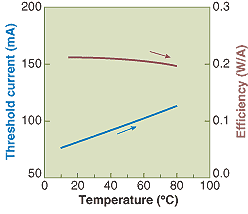
Thermal management is another important dimension of laser-diode test. The diode current threshold depends on the laser temperature. Typically, the threshold will increase exponentially with temperature.
Although not as apparent as threshold shift, laser efficiency falls off with increasing temperature (see Fig. 2). To test at the bar and die stage a rise in junction temperature of 40°C/W to 80°C/Wcaused by the thermal resistance of the devicemust be overcome. Materials used to mount the device for test must provide mechanical and thermal stability. Temperature data must be acquired and processed quickly. Computer-based thermal-management techniques can provide control from 0°C to 110°C at 0.1° resolution with high-speed data-acquisition hardware, a Peltier heat pump, a heat sink, and a pedestal. A pedestal with a proprietary alloy developed by AmFax provides a 10x improvement in thermal agility, for example.
Single-mode alignment
With major environmental factors such as temperature and vibration under control, the next step is to align the parts. Integration of motion, vision, optical, and electrical measurements are necessary for alignment. Fine optical alignment ensures that the coupling of single-mode fiber is optimally located in front of the device under test (DUT) emitting facet. Software can integrate and synchronize all functions such as the controlling vacuum, microprobe positioning, and laser-diode current. Applications achieve the best performance with hardware synchronization of motion and measurements controlled by software using PXI, which integrates measurement, timing, and triggering.
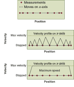
The improved performance from such an integrated system enabled equipment manufacturer JDS Uniphase (San Jose, CA) to increase production 8 to 15 times. The test machine measures optical power during a search of a predetermined spatial volume in X, Y, and Z. With hardware synchronization of motion and optical power, the optical power and the position are simultaneously recorded during the movement, enabling fast large area measurements and change in trajectories (see Fig. 3). Synchronization improves throughput by eliminating nonsynchronized move-stop-measure approaches that do not accurately correlate power measurements with position unless movement is completely stopped. The fiber is then locked in the position of peak power to carry out testing. A system using nanopositioning and piezo-actuated stages, controlled by synchronized motion and data-acquisition sweeping a volume of 100 μm3, completes testing in less than 4 s, with 1 to 1.5 s achievable with certain laser-diode products.
Component tests
The most common tests carried out on laser diodes at the bar and die stage are electrical and spectral. Typically the diode integrity is checked first. Next, light-current-voltage (LIV) characterization is performed, which requires either a wide-area detector (WAD) or an integrating sphere. In this automated process, the fiber and WAD are mounted on a separate stage and alternately placed in front of the DUT. As many as 300 points are required in LIV testing. Due to the data transfer limitation of serial interfaces, a 300-point LIV takes approximately 8 to 10 s and requires special programming. To overcome serial interface limitations, optoelectronics manufacturers use PXI instruments cut a 300-point LIV test time to 2 s.
Several manufacturers of semiconductor laser diodes around the world have used the AmFax solution in a customized form. In one case, in which 26 systems are installed, yield improved from 40% to 80% after delivery of the first system. Development of test techniques, reliable probing, and alignment increased yield to 92% and reduced the test time from 65 to 15 s. A major contributor to the success of these solutions is the adoption of an open standard, compatible with all major suppliers of test equipment and industry-standard programming languages. System development is based on the evolution of open standards rather than "black-box" closed systems, which means a lower cost, shorter lead time, and higher level of confidence in the end product (both test solution and laser diode).
ARMANDO VALIM is optoelectronics market manager at National Instruments, 11500 N. Mopac Expwy., Austin, TX 78759-3504; e-mail: [email protected].


