JOHN HAYES
Mechanical vibration and turbulent airflow present significant problems for most interferometric test methods. Conditions on the factory floor and in industrial clean rooms with high-capacity air filtration systems, for example, can hamper the use of interferometry. Another key problem area is the testing of large-aperture mirrors (1 to 10 m) when it is difficult to mechanically isolate such mirrors and the structures needed to support the optical test; in addition, long optical paths produce air-turbulence problems. To make things worse, the next generation of large-aperture lightweight mirrors for space-telescope applications must be tested in large vacuum chambers at cryogenic temperatures—a situation in which vibration is virtually impossible to control.
The methods most often used to overcome the problem of vibration are high-speed static interferogram capture and slope-sensitive tests such as the Shack-Hartmann wavefront sensor or shearing tests. High-speed static interferogram capture requires a static fringe analysis that sacrifices speed, spatial resolution, and accuracy. The Shack-Hartmann test can achieve fairly good accuracy (1/20 wave) but suffers from low spatial resolution (generally about 100 x 100 data points is a maximum).
The problem with traditional phase-shifting interferometric (PSI) techniques is that data is taken sequentially over a fairly long period of time. Most commercial phase-shifting interferometers use standard video-rate cameras and take at least four or five frames of data to compute a phase map, which means that the interference pattern must be stable for 120 to 150 ms to get good data. At that data rate, the vibration frequency cannot be much higher than about 0.5 Hz. Because most normal floor vibration occurs in the range of 20 to 200 Hz, traditional PSI systems must be mounted on a vibration-isolation system.
Given the advantages of PSI measurements, a number of vibration-tolerant solutions have been developed. Here we briefly review a range of the solutions that have been successfully implemented.
Single-frame measurement
Carl Zeiss (Oberkochen, Germany) developed one of the first commercial, single-frame, phase-measurement systems. The design used a Fizeau interferometer to introduce a large amount of tilt (about 200 fringes across the aperture) between the test and reference beams. The amount of tilt in the reference beam must exceed the maximum wavefront slope so that no closed fringes are produced. All of the internal optical components are well-corrected for large amounts of tilt between the two beams to minimize instrument errors in the results. A spatial-carrier phase-shifting method computes the wavefront phase modulo 2π. The data are treated as a set of very small windows that essentially contain tilted flat wavefronts. The convolution process limits the accuracy within a pixel or two from the edge of the pupil, but this limitation is not serious.
When this instrument was introduced in the early 1990s, the speed requirements to reach 30 fps could only be met with custom processors and circuitry, which were large, complex, and expensive. In spite of the high cost of these systems, they worked quite well in situations that required true single-frame phase-measurement speed. ADE/Phase Shift (Tucson, AZ) has recently introduced a system that uses a Twyman-Green interferometer with a similar carrier frequency demodulation technique.
Four images on four detectors
The simultaneous phase-shifting interferometer (SPSI), commercialized by ADE/Phase Shift, produces true video-rate phase measurement from four detector channels. The concept is fairly straightforward. Polarization components are used with a Twyman-Green interferometer to produce four images of the test pupil, each shifted in phase by 90° with respect to each other. A video camera placed at each image feeds data to four separate frame grabbers in a single computer.
Many problems must be overcome to make this approach work well. First, all four cameras must be very carefully aligned in both position and angle with respect to each of the images. Small misalignments will affect the spatial frequency response and accuracy of the system. Second, the cameras must be carefully synchronized so that data is taken at the same time. Third, the polarization components in the interferometer must be carefully chosen and aligned to produce precise 90° phase shifts, equal intensity, and uniform images. Finally, the mechanical and thermal stability of the instrument must be sufficient to maintain alignment when the system is moved or the environment changes. Despite the practical difficulties, this type of system offers high spatial resolution and the capability of real-time phase display.
Four images on one detector
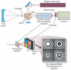
An interferometer developed by 4D Vision Technology Inc. (Irvine, CA) provides a clever solution to the camera alignment issue inherent in the SPSI configuration. A polarization Twyman-Green interferometer with a two-dimensional grating at the exit pupil produces four images of the pupil on a single high-resolution detector (see Fig. 1). A phase mask placed in the image plane produces the required 90° phase shifts for each image. The cleverness of the PhaseCam is that all of the data is stored on a single frame, completely eliminating camera alignment and synchronization issues. Another advantage is that the optical system is quite simple and can be packaged in a relatively compact housing. Care in implementing the beamsplitter grating and polarization optics is necessary to produce high accuracy.
The most significant limitation to this approach is that the spatial resolution of the computed phase map will be one-half the resolution of the image sensor. Since 4-megapixel detectors are readily available, 1000 x 1000 pixel phase maps can be easily produced. Finally, it is straightforward to equip this type of system with a high-speed camera or shutter to acquire data at very high speed. With a fast-enough camera, measurements can be made with virtually any amount of vibration or air turbulence.
Random data acquisition
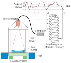
Workers at the University of Arizona Mirror Lab have developed another clever method that actually uses vibration as a phase-shifter to measure large-aperture mirrors. The test mirror, usually in the range of 6 to 8 m in diameter, is placed face-up under a vibration-isolated test tower. A standard interferometer is mounted at the top of the tower looking down at the mirror and is aligned to produce interference fringes on the test mirror. A Twyman-Green interferometer is used, but a Fizeau would also work. Although the test tower is isolated from vibration, the structure is so large that low-frequency, high-amplitude vibrations are always present. The trick is to use a high-speed video camera running at about 200 frames/s to record a large number of interferograms (see Fig. 2).The data are typically stored in computer memory and processed in batches of 72 frames. Software is then used to analyze the relative phase shift and contrast of each image. The algorithm looks for five frames with the required 90° phase shifts and good contrast. A standard phase-shifting algorithm is then used on the five frames to compute the shape of the mirror. The technique works well because the large mirror is mostly vibrating in "piston" mode with respect to the interferometer so that higher-order modes (such as tilt) are very small. The primary challenge is to remove the effects of air turbulence. In this case, the turbulence is random and slowly changing so that averaging statistically uncorrelated data over a long enough period of time effectively reduces the impact of turbulence. The system is set up to run automatically and typically produces a high-quality result in 15 minutes to one hour. The test system is mounted under the University of Arizona football stadium and works so well that excellent data have been taken during a game.
Active vibration compensation
Another approach to handling vibration is to sense the vibration signal and cancel it in the interferometer. This is the same concept used in modern noise-canceling audio headsets. It turns out that the vibration of a rigid object generally produces a large piston term, smaller tilt terms, and much smaller higher-order terms. In the absence of massive air turbulence, the piston term is usually the predominant factor—sometimes producing hundreds of fringes of displacement. Based on this fact, a simple, high-speed piston correcting active-compensation system was developed by J. H. Burge and G. C. Cole and later refined by the author at the University of Arizona.
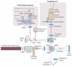
In the later system, a real-time point-phase sensor is added to a polarization Twyman-Green interferometer (see Fig. 3). The phase is stabilized to a setpoint signal supplied by a standard phase-shifting piezoelectric controller through a digital feedback loop driving an electro-optic phase modulator. The feedback loop can handle frequencies up to about 0.5 kHz and corrects the phase to modulo 2p so that virtually any amount of piston error can be handled. Because the setpoint signal is taken from a standard piezoelectric controller, any commercial multiple-frame phase-shifting computer can drive the system.This approach works amazingly well for piston vibration that occurs within the bandwidth of the feedback loop. With the feedback system turned off, the fringe pattern may be moving so fast that it is invisible. Switching on the control loop instantly freezes the pattern, enabling very-high-quality phase measurement. The big limitation of this approach is that only low-order vibration can be handled. Although not yet implemented, vibration due to tilt could be handled with a separate tilt sensor and a second feedback loop. Likewise, only low-frequency air turbulence can be measured and reduced by data averaging.
John Hayes is a research professor at the Optical Sciences Center, University of Arizona, 1630 East University Boulevard, Tucson, AZ 85721; email: [email protected].


