Conventional testing methods for devices such as microwave or millimeter-wave structures, integrated circuits (ICs), antennae, and arrays are finding competition from electro-optic sampling in applications mapping the near-field region of the free-space electric field. Unlike alternatives such as open-waveguide, near-field scanning, and far-field detection that can introduce metal into the near-field region or have limited spatial resolution, the electro-optic technique provides high-resolution two- or three-dimensional feedback. There are limitations, though, which are mostly related to the large microwave permativities for the bismuth silicate (BSO) and lithium tantalate (LiTaO3) probes. These distortions can lead to distortion of the local electric-field distribution surrounding the probes.
While gallium arsenide (GaAs), with its relatively small dielectric constant, seems a good alternative, it has been limited to normal-field component detection. This may change, though, with the word that researchers at the University of Michigan (Ann Arbor, MI) have devised a sampling system that can map three independent orthogonal components of free-space electric fields with external GaAs probes.1
The crystal orientation is the primary reason it has taken so long to produce a GaAs-probe-based mapping system competitive with others based on BSO and LiTaO3 crystals. According to John Whitaker and colleagues at the university's Center for Ultrafast Optical Science and the Radiation Laboratory, the index of refraction for (100)-oriented GaAs is sensitive to the component of the electric field that is polarized perpendicular to the (100) surface, but this fact alone is not sufficient to replace the other two crystal types, which map in three dimensions.
Because of its zincblend lattice crystal structure, GaAs has an identical structure in (100), (010), and (001) orientations, each of which has normal-field sensitivity. To maximize sensitivity in the electro-optic modulation, both the incident laser probe-beam direction and the RF polarization should be normal to the plane in each case. Align the incident laser beam normal to the (110) plane, however, and the GaAs crystal shows sensitivity to the RF field component that is parallel to the plane. This allows that GaAs crystal structure to detect tangential field components. The mapping system devised at the university is thus able to offer complete maps of three orthogonal field components by using two GaAs electro-optic probes with different crystal orientations.
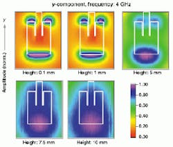
During the experiments, GaAs probes were fabricated with a simple cleaving process. To detect the field perpendicular to the surface of the devices, researchers cleaved a 600-µm-thick wafer with (100) orientation into a cube so that it had 1 x 1-mm2 facets on the bottom and top. To provide tangential field sensitivity, they fabricated a 400-µm-thick (110) wafer with 1 x 1-mm2 facets. The scientists then compared field maps for a 4-GHz microstrip patch antenna produced with the GaAs probes with a system based on the other two crystal types (see figure). According to Whitaker, the principal difference was the requirement for a longer laser wavelength to keep the probe-beam photon energy below the GaAs bandgap.
Test results indicated comparable feedback for all three orthogonal fields, with the GaAs (100) probe yielding superior results to the BSO crystal probe in terms of high definition for both amplitude and phase mapping.
REFERENCE
- K. Yang, L. P. Katehi, and J. F. Whitaker, Appl. Phys. Lett. 77, 486 (July 24, 2000).
