LASER DIAGNOSTICS: Time-resolved beam profilers can take the heat

RAHUL R. PRASAD and JOCHEN SCHEIN
Laser beam profilers measure the spatial distribution of intensity in a laser beam. Most profilers provide a single profile of a single pulse from a pulsed laser, but a new class of profilers is emerging—these use an array of fast photoconducting detectors to provide a time-resolved (subnanosecond resolution) profile of a single beam pulse. These devices also are not susceptible to damage and can be placed directly in the path of high-intensity beams, thus eliminating the need for beam optics that may distort the measurement. These profilers can work with ultraviolet (UV) and visible lasers.
Primer on profilers
Laser beam profilers can determine the spatial profile of laser beams used in a variety of applications. They can be subdivided into two types—electronic and nonelectronic beam profilers. Nonelectronic profilers, such as burn paper, fluorescent beam cards, and acrylic mode burns, find widespread use in science, the military, and industry because of their upfront cost advantage compared to electronic systems.
Burn paper is widely used to measure the intensity distribution of lasers. It gives a rough order of magnitude of the beam size and can show some structure of the profile pattern. This method can capture only a single laser pulse, and—most disturbing—it has a dynamic range of only three, one level for unburned paper, one for black paper, and one for paper turned to white ash. This does not provide sufficient accuracy to perform any quantitative work with lasers. In addition, burn paper will not show significant hot spots or holes in the beam, effects that can appear because of misalignment of the laser cavity.
Another method involves fluorescent cards and relies on the detection of diffused light by the eye. This is also a qualitative method of beam profile measurement. The eye is a logarithmic detector and can see many orders of magnitude in signal intensity. Even when a good Gaussian beam is present, the eye will tend to give the impression that the beam is much larger than the e-2 width, often by as much as a factor of three. There may (or may not) be much energy at the circumference of the pattern. One problem is that the eye cannot discern changes in beam intensity that are smaller than a factor of two to ten. Thus, the eye is not a good indicator of either the quality of the beam or the beam width. Additionally, this method cannot be applied to high-power lasers because of safety issues.
Another option in this category, acrylic mode burns, works well for CO2 lasers. But acrylics create toxic fumes, suffer from the same drawbacks as other nonelectronic profilers, and are not able to provide information for pulsed laser beams.
Electronic methods of beam profile measurement include scanning knife-edge profilers, scanning-slit devices, and systems based on charge-coupled-device (CCD) cameras. With knife-edge profilers, a metal edge is moved through the beam path. As the blade moves across the beam, light is blocked from reaching a single photodetector and the measured signal continuously decreases to zero. The measured signal has to be differentiated to obtain a beam profile.
The advantages of these instruments include their high spatial resolution (up to 100 nm) and their ability to analyse beam power when the detector is fully exposed. There are also several disadvantages of such systems; they cannot work with high-power lasers (the detector would be destroyed) or with pulsed lasers (no mechanical system can deliver a time resolution of less than a nanosecond). In addition, a knife-edge profiler can perform beam analysis in only one dimension.
Scanning-slit devices encounter the same disadvantages as the knife-edge profiler, except that they can be used for high-power lasers. The use of a small slit attenuates the laser beam sufficiently to protect the detector. Silicon-based CCD camera systems, which consist of a two-dimensional (2-D) array of rectangular pixels, can be used for continuous-wave (CW) and pulsed lasers. The resolution, however, is limited by the pixel size (15-20 µm), and the methods required for attenuation of high-power laser beams can distort the beam intensity distribution. Typical saturation levels of CCD detectors are about 50 µJ/cm2 at 248 nm. To use these CCD detectors for high-power laser beam analysis, several different techniques have been devised to attenuate the light intensity at the CCD, ranging from simple attenuators to beam sampling using different types of beam-splitting optics.
Another disadvantage of a scanning-slit device is the low repetition rate—limited to the video rate of 30 frames/s and the usual dynamic range of 256 gray levels. Time resolution within a single laser pulse (<10 ns) is impossible.
Nanosecond-level temporal resolution
A new kind of laser beam profiler provides temporal resolution of up to 0.5 ns within a single laser pulse. This instrument is based on a chemical-vapor-deposition (CVD) diamond detector array, with individual pixels fabricated with metal deposition on the diamond. These pixels are read using fast digitizers to provide the high temporal resolution.
Prototype arrays of 16 1-mm2 pixels (arranged in a 4 × 4 pattern) have been fabricated and tested with a high-power laser. These arrays are sensitive to radiation ranging from the green (532 nm) to the UV. The profilers work with most common types of lasers, ranging from solid-state systems such as Nd:YAG to gas lasers such as excimer devices. The damage threshold of the detector array is higher than 100 MW/cm2, which allows inserting this class of laser beam profilers directly into the laser beam without the use of attenuating (and thus beam-distorting) optics.
One such beam profiler was tested using a Nd:YAG laser (Continuum; Santa Clara, CA) with 10-mJ output power at 355 nm in a pulse of 6-ns maximum duration (see figure). The profiler was inserted directly into the laser beam. Each pixel was biased with 100 Vdc. The signal from each detector was fed into an oscilloscope with a 50-W input impedance. A 1-ns temporal resolution was achieved using 1-Gsample/second sampling-rate oscilloscopes. The profile of the laser beam changed as a function of time within a single shot.
A signal like the one in the figure was obtained for each pixel on every shot. By using the internal trigger output of the laser, the device allowed synchronization of all signals. Two-dimensional images of the laser pulse were obtained by taking signal values from each pixel at different times in the laser pulse. A sequence of such images was created for every shot, providing details of the temporal evolution of the laser pulse (see "A beam in time").
In summary, conventional electronic and nonelectronic beam profiler devices fall short in one or more of the following ways: dynamic range (burn paper, eye-based systems, CCD); profiling high-power lasers without using additional beam-distorting optics (eye-based systems, knife-edge, CCD); two-dimensional resolution (knife-edge, scanning slit); spatial resolution (burn paper); repetitive measurements—faster than 30 Hz (all); and temporal resolution—ability to resolve a 10-ns pulse (all).
The temporal-resolution class of beam profilers overcomes most of these limitations. One potential drawback of these profilers, however, is that each pixel must be digitized individually, limiting the number of pixels in a practical system. This drawback is overcome by using delay lines to delay signals from each pixel into a single digitizer channel. Signals from each pixel are later reconstructed using software.
The resolution of the prototype profiler was 1 mm2. This may easily be increased to as much as 100 µm2 or possibly even better, by using common lithographic techniques to form the pixels on the diamond substrate.
Rahul R. Prasad is principal scientist and Jochen Schein is a scientist with Alameda Applied Sciences Corp., 2235 Polvorosa Avenue, Ste. 230, San Leandro, CA 94577; e-mail: [email protected].
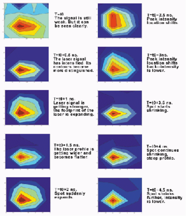
A beam in time
Image series shows the variation in spatial distribution of a laser beam within a single laser pulse. These 4-mm2 images were acquired with 0.5-ns resolution within a single ~5-ns laser pulse from an Nd:YAG laser. Such data can be obtained only by using a temporally resolved laser beam profiler.