INTERFEROMETRY: Encoder measures motion through interferometry
Opher Kinrot and Uri Kinrot
Encoders translate motion into electronic signals, which can then be used to monitor the motion. The most common encoders are optomechanical, in which motion of a mechanical encoding unit—such as a slotted wheel—interrupts the optical path between a light-emitting diode (LED) and a detector. All-optical encoders using noncoherent illumination contain image-correlation sensors, which compare consecutive images to deduce object motion. The accuracy of the encoder derives from identification of high-contrast features of the object (such as edges) and is thus dependent on the object and its illumination properties.
Unlike their noncoherent counterparts, coherent encoders do not rely on object features; instead they use interference with its intrinsic wavelength scale for encoding motion. A basic coherent encoder is the Michelson interferometer, used in high-precision motion systems. However, it requires a stable measurement setup and precise optical alignment. The encoder measures axial motion along the illuminating beam direction. Coherent methods that measure transverse motion—parallel to the measured surface—include speckle methods1 and laser Doppler velocimetry.2 Both suffer from a low signal-to-noise ratio (SNR), with speckle methods also being sensitive to the distance from the measured surface.
Optical translation measurement (OTM) is a novel technology owned by OTM Technologies Ltd. (London, England) and developed by its affiliate GOU Lite Ltd. for coherent encoders measuring one-, two- or three-dimensional motion. The OTM encoder measures the relative motion of surfaces placed adjacent to its aperture at a distance of zero to a few millimeters, using diffusive light reflected by the surface. The method offers high SNR, high accuracy, and resolution of a few wavelengths. It is not sensitive to the type of the surface being measured nor to the distance between the surface and the encoder.
Basic device
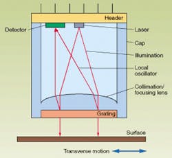
A basic OTM device includes a laser light source, collimation lens, grating, focusing lens, one or more detectors, and signal-conditioning electronics (see Fig. 1). The laser light is collimated by a lens and directed toward the surface being measured. The optical grating is placed between the laser and the surface, reflecting part of the light as back-diffracted orders that serve as local oscillator (LO) beams. The diffuse light reflected from the surface and the LO light are both focused onto the detectors by the focusing lens, so that each detector measures a single LO beam. The spacing between the surface and the grating should be smaller than the coherence length of the light, given by ~~l2/Dl, where Dl is the spectral width and l the wavelength of the laser. The LO beam and the reflected light are thus inherently coherent, and the detector measures the interference signal between them—this is called homodyne detection.
The LO light is focused to a small spot on the detector surface, while the diffuse surface reflection creates a broad speckle pattern. The only part of the surface reflection that interferes with the LO light is the part parallel to the LO beam direction; thus it is focused to the same location on the detector. The intensity of the LO beam is much larger than the surface reflection intensity on the detector, with the result that the interference performs selective amplification that amounts to spatial filtering of the diffusive reflected surface light.
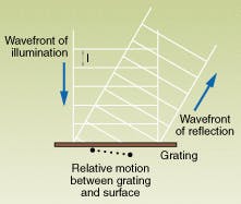
The resulting detector signal varies with changes to the relative phase between the LO beam and the surface reflection, corresponding to the relative translation of the device and the surface (see Fig. 2). Electronic signal conditioning by an amplifier and band-pass filter results in a clean, time-varying signal representing the motion. Counting the "zero crossings" of the oscillating signal gives a direct measurement of the magnitude of translation, regardless of motion velocity.The use of a near-surface grating to generate LO beams for coherent detection of diffuse reflected surface light allows the creation of a self-contained, robust device with simple electronics of a size similar to standard transistor-style packages. Because the only requirement from the surface to be measured is some diffuse reflection, the encoder works equally well on featureless paper and lined wood samples, as well as cloth, skin, and most other surfaces. A single encoder using a 2-D grating can measure full 3-D motion. The encoder resolution is set by the grating period, and the accuracy depends on the illuminated grating size (see "Giving dimension to measurements").
Applications
We are working toward commercialization of several potential applications of OTM. These include an OTM component embedded in a laptop, palm computer, or remote-control unit. The component is a stationary pointing device operated by moving a finger across its aperture. The aperture size is about 5 mm2, and the finger glides across it, moving only a few millimeters in any direction. Resolution in excess of 2000 dpi and large dynamic range enable translation of sensitive finger motion to accurate and stable cursor motion on the screen. Tapping with the finger is optionally identified as "click" and "double click," enabled by 3-D motion encoding. Such a device would be based on a vertical-cavity surface-emitting laser (VCSEL).
A "virtual pen" can be used to digitize text written with it on paper by tracking the pen motion and using optical character recognition (OCR) software. The look, feel, and usage of the encoder pen is identical to a regular pen—it writes on any surface (like paper) and can use ink as well. The pen includes an embedded OTM component near its tip to encode the tip's motion and a remote link to a computer, cellular phone, or interactive Tv receiver. The 3-D tracking ability of OTM enables identification of characters involving a few pen strokes, such as 't' or 'x', as well as identifying separate words. Standard OCR software translates natural handwriting of separated characters into inputs to the host device, replacing the need for a full keyboard.
Unlike standard paper drive encoders, which measure the motion of the drive mechanism, an OTM encoder can measure directly the motion of paper in printing, copying, or fax machines. This enables both synchronization of paper motion through-paths and identification of malfunctions in the drive mechanism operation. One-dimensional OTM edge detectors are single-sided and can be made to respond only to objects moving with a given minimum velocity. In addition to providing robust and accurate edge identification, the paper motion is continuously monitored.
An OTM device is typically integrated into a small transistor-style package, using a solid-state laser and molded plastic optics. The packaging, the coherence requirements from the laser, and the expected mass-market applications for OTM encoders all make VCSELs a natural choice for use in OTM. Requiring typically less than 1 mW of laser power, an OTM encoder using a low-power VCSEL can be mass-produced at a very low unit cost, creating a new and large potential market for single-VCSEL devices. Edge-emitting lasers can also be used, especially for applications requiring high optical power or short wavelength.
REFERENCES
- U. Schnell, J. Piot, and R. Daendliker, J. Opt. Soc. Am. A, 15, 207 (1998).
- H. T. Yura, S. G. Hanson, and L. Lading , J. Opt. Soc. Am. A, 12, 2040 (1995).
OPHER KINROT is chief technology officer and URI KINROT is vice president, R&D, at GOU Lite Ltd., 85 Medinat Hayehudim, Herzliya 46766 Israel; e-mail: [email protected].

