A 'heated' topic: Laser calorimeters
Ronald E. Vander Haeghe
Laser calorimetry is the measurement of laser-pulse energy by measuring the increase in temperature of an optical absorber irradiated by a laser beam. Historically, calorimeter development has been driven by the varying needs of its users, such as wavelength(s) of operation, beam size, energy level to be measured, and laser fluence. Other considerations are susceptibility to the environment, calibration to primary electrical standards, pulse duration, and the interval between pulses.
Several types of laser calorimeters have existed, some of which are still in use. Dual-aperture, ballistic calorimeters were used to measure multimillisecond pulses from 100-J pulsed industrial Nd:glass lasers. In this case, the second aperture was used to null the influence of stray light and the thermal ambient. Back-to-back twin aperture windowed calorimeters have been designed to measure average power over short periods of about two minutes and energy of pulsed laser bursts, single pulses, and timed continuous wave (CW) pulses lasting tens of seconds. Some of these are still used in calibration labs and occasionally as transfer standards by the National Institute of Standards and Technology (NIST) Measurement Assurance Programs.
Over time, NIST has designed many vacuum-insulated optical-cavity electrically calibrated calorimeters, for use as primary standards. These have capabilities ranging from 1 µW to 200 kW continuous wave, 5 mJ to 6 MJ (pulse over a long time period), and 193 nm to 20 µm. They typically have not been designed to measure single-pulse energies for pulse durations of less than one second.
In the past, fusion-laser systems have used 200-mm-aperture calorimeters. These were large-aperture, convection-cooled wattmeters built with neutral density absorber glass (for volume absorption) mounted on aluminum heat diffusers. They used the Seebeck effect, the basic property of a thermocouple of Peltier modules, to measure heat. An array of Peltier modules, mounted between the diffuser and a heat sink, generated a voltage pulse proportional to applied energy. These were designed to measure 500 J or less at 1053 µm with nanosecond duration pulses.
For larger, higher-energy beams, the NOVA laser and initially the "beamlet" laser used, respectively, 74- and 76-cm aperture "beam-dump calorimeters" to measure up to 12 kJ of 3 ns duration laser pulses of combined 1w, 2w, and 3w laser energy (1w = 1.053 µm).1,2 These calorimeters consisted of an array of 6-in.-square panes of neutral-density glass bonded to an aluminum heat diffuser mounted on thermally insulating spacers. Here, an array of thermocouples was physically bonded to the heat diffuser and serially connected with an equal quantity of reference thermocouples bonded to a thermal reference plate. This thermocouple array measured the temperature increase of the glass absorber. The resulting pulse response sensitivity for this device was approximately 140 µV/J. The incident laser beam flux applied to these calorimeters was typically <3 J/cm2 or <3 GW/cm2, limited by the coefficient of absorption of the glass absorber and also probably by the optical defects presented by the gaps between the glass panes.
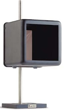
Currently, calorimeters vary from small, commercial, optothermal wattmeters used in pulse mode to large-aperture, high-energy calorimeters used in the vacuum instrument tunnels found in laser-fusion systems (see Fig. 1). Mathematical models have been developed in the past ten years that permit reasonable predictions for the temporal shape and the amplitude of the pulse response of these calorimeters.
Small calorimeter
An example of the use of standard wattmeters as small calorimeters is a 19-mm aperture, convection-cooled, average power wattmeter (typically 3 to 10 W maximum), using neutral-density absorbing glass or other absorbing materials bonded to a Peltier element. These use the Seebeck effect of a Peltier module to generate a voltage pulse proportional to the temperature increase between the absorber and a heat sink to which the Peltier is also bonded. The temperature increase is directly proportional to the applied energy. The resulting calorimeter sensitivity is stated in V/J and is the foot-to-crest voltage value of the pulse response. Since the heat sink of a calorimeter/wattmeter is designed to dissipate the heat of continuous power, thermal isolation in an isoperibol enclosure is usually required at low energies, to limit fluctuating heat exchange with the surrounding environment that causes erratic measurements.
Light of different wavelengths is absorbed at different depths in volume-absorbing media because the coefficient of absorption varies with wavelength. The resulting dynamic response of the volume-absorbing calorimeter will vary with wavelength, causing the rise time to speed up and the peak amplitude to increase as light is extinguished deeper in the volume absorber. The thicker the absorber and the deeper the light is extinguished in it, the greater the dynamic response variations observed.
In the above small calorimeter/wattmeter a 0.5-mm thick NG-1 glass absorber will have a step response of about 100 mV/W with a 1/e rise time of about 10 s (this is the response to application of continuous average power). Its single-shot pulse response is 10 mV/J at 1.064 µm with a 0% to 100% rise time of 400 ms and a 1/e decay time of approximately 10 s. This device has a practical dynamic range of 100 mJ to 10 J at 1.2 µm, limited by the coefficient of absorption and the resultant fluence damage threshold. This small calorimeter can accept pulse durations up to the 10% to 90% rise time of the pulse response.
Large calorimeter
A few years ago, Gentec worked with the Laboratory for Laser Energetics of the University of Rochester (Rochester, NY) to design and build a large-aperture, high-flux calorimeter for beam balancing its "Omega Upgrade" laser (see Fig. 2). The project involved researching and designing a single-component, volume-absorbing media, as well as a high-damage threshold antireflection coating compatible with the three wavelengths of interest. The resulting device was a 31-cm clear aperture, volume-absorbing calorimeter, designed to measure from 200 J up to 1.5 kJ of combined 1w, 2w, and 3w laser energy (1w = 1.053 µm).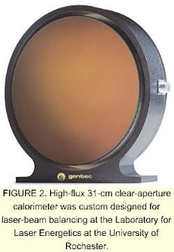
Because the large calorimeter measured the energy of three different wavelengths of laser light in unquantified proportions, the peak response technique could not be used for the reasons explained above (small calorimeter). Instead an electronic integration technique was used to measure the area under the curve of the pulse response. The calorimeter had a sensitivity of approximately 1.06 x 10⁻¹ Vs/J. Contrary to the peak voltage response, the area-under-the-curve response was insensitive to the depth of light penetration in the absorber and consequently to the point of injection of heat in the absorber. This attribute also permitted the characterization and calibration of the calorimeter by a pulsed-equivalent heat source such as a low-mass electric heater.
Contrary to the free-convection cooling design of the small calorimeter, the sensor assembly of the large calorimeter, which also included a massive heat sink, was thermally isolated inside an outer housing. Additionally, the glass absorber of the sensor was closely mounted near a transmissive optical component and the outer housing was gasket-sealed to the laser beam tubes. This whole thermal-isolation technique was rendered necessary by the large surfaces of both the absorber and the heat sink. While the calorimeter thermally integrated 1-ns optical pulses over a period of more than 800 s, the large surfaces were cooled by convection and radiation. This will cause strong fluctuations in the dynamic response and area under the curve if the rate of cooling fluctuates due to drafts, stray light or heat radiation.
Many of these large-aperture calorimeters, hinged at the end of each beam tube, are now used in a cleanroom environment to measure the energy in each beam. The resulting measurements are used to adjust the lasers and balance each beam so that when the lasers are fired into the target chamber, implosion symmetry of the fusion target is optimized.
Whole-beam calorimeter
More recently, Gentec built a calorimeter to be used as a whole-beam calorimeter for Lawrence Livermore National Laboratory's "beamlet" laser (Livermore, CA), to be used in the Focal Plane Diagnostics Package. The 31-cm clear aperture calorimeter was re-engineered to be used in a vacuum (10-6 torr) to measure 20 to 500 J of combined 1w, 2w, and 3w laser energy (1w = 1.053 µm). In this case the absorber was required to have an optical damage threshold of <3.2 J/cm2 at 351 nm with a pulse width of 3 ns.
The main challenge was to render vacuum compatible nearly all the materials and components used to build the calorimeter and to decrease the minimum measured energy by an order of magnitude. While the minimum energy requirement was simplified by the fact that the calorimeter was to be used in a vacuum, all the testing, characterization and calibration work had to be executed in a vacuum chamber.
The resulting calorimeter generated a single-pulse response of about 650 µV/J with a 0% to 100% rise time of approximately 23 s and a 1/e decay time of about 208 s. The slower decay time was caused by the greatly reduced heat exchange between the calorimeter and the vacuum ambient. The calorimeter had an area-under-the-curve pulse response sensitivity of approximately 90 x 10-3 V s/J (up to the 1/e fall point). The 1/e fall point was chosen as the limit to measured sensitivity because past this point offset fluctuations became sufficiently important to degrade the repeatability of the measurements. This same calorimeter will be used in the Precision Diagnostics Package of the National Ignition Facility (Livermore, CA).3
Future calorimeters
Larger apertures will be the driving force in calorimeters in the future, along with higher energy measurements. The direct consequence will be ever-increasing energy and peak power density requirements. Another challenge will be to reduce the calorimeter footprint. Currently, the available types and dimensions of neutral-density filter glass are major limiting factors in high-energy calorimeters. Larger surfaces consisting of segmented or tiled arrangements of smaller filter plates are limited in damage threshold by gaps and ridges between plates. The damage threshold of these flaws will always be lower than that of the filter glass.
To exceed current damage threshold limitations, much work remains to research and produce new absorbing media (volume or surface). These new media must be capable of withstanding much higher laser fluences in the ultraviolet than filter glass, while remaining thin enough to limit the calorimeter footprint and prevent important thermal mass contributions to the calorimeter that reduce sensitivity and slow down the response.
RONALD E VANDER HAEGHE is the technical coordinator in the Electro-Optics Division of Gentec Inc., 2625 Dalton, Ste-Foy, Québec, G1P 3S9 Canada; e-mail: [email protected].
References
- S. C. Burkhart et al., "Beamlet Laser Diagnostics," Lawrence Livermore National Laboratory (1995); www.llnl.gov.
- B. M. Van Wonterghem et al., "System Description and Initial Performance Results for Beamlet," Lawrence Livermore National Laboratory (1995); www.llnl.gov.
- R. D. Boyd et al., "Alignment and Diagnostics on the National Ignition Facility Laser System," Lawrence Livermore National Laboratory (1999); www.llnl.gov.