UV OPTICS: Primary mirrors figure well for space spectroscopy

Optical testing of the Far Ultraviolet Spectroscopic Explorer primary mirrors demonstrates their readiness for space science.
Raymond Ohl, Timo Saha, Robert Barkhouser, Scott Friedman, and H. Warren Moos
The Far Ultraviolet Spectroscopic Explorer (FUSE), successfully launched on June 24, 1999, is an astrophysics satellite designed to provide high spectral resolving power (lambda/Deltalambda of 24,000-30,000) and large effective area (20-70 cm2) over the wavelength interval of 90.5-118.7 nm. The instrument consists of four normal-incidence, off-axis parabolic primary mirrors that illuminate separate Rowland-circle spectrograph channels equipped with holographic gratings and delay-line microchannel plate detectors (see Fig. 1).
The FUSE wavelength range is rich in spectral lines arising from stellar and interstellar gas, providing the opportunity to make important contributions to many areas of astronomy. In particular, FUSE will measure the abundance of deuterium in a range of astrophysical environments to determine the extent to which stellar processing has modified the primordial abundance of deuteriumthereby providing a better understanding of the amount produced in the Big Bang and the subsequent change in abundance as the universe aged.1
Stringent imaging requirements
To meet mission goals, the FUSE mirror team built primary mirror assemblies that were lightweight, maximized the instrument's effective area in the bandpass, and met a stringent imaging requirement of 90% encircled energy (EE) within a diameter of 1.5 arcsec at a wavelength of 100.0 nm. We designed an instrument featuring four mirrors (387.0 x 351.8 mm, 2245-mm focal length with 5.5° off-axis angle), one for each FUSE ultraviolet (UV) channel. The mirrors are made from aggressively weigh-relieved (or "lightweighted") Zerodur blanks, in which 70% of the substrate material was removed from each blank (see Fig. 2). Two mirrors are coated with ion-beam-sputtered silicon carbide (SiC), and the remaining two are coated with lithium fluoride (LiF) over aluminum, to maximize reflectivity from 90.5-110.3 nm and 98.0-118.7 nm, respectively.
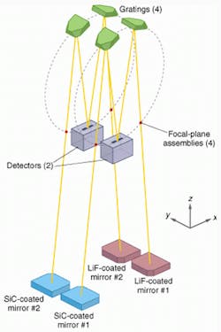
RIGHT. FIGURE 1. Optical design baseline for the Far Ultraviolet Spectroscopic Explorer includes four spectrograph channels. Two mirror segments coated with silicon carbide (SiC) reflect optimally at the shorter end of the instrument's wavelength range; two mirrors coated with lithium fluoride (LiF) reflect optimally at longer wavelengths.
In order to meet imaging requirements, nearly the entire power spectral density of mirror surface error was specified, with special attention to the mid-frequency 0.1-10.0-mm spatial scales. Fabrication specifications for the FUSE mirrors were derived from information on SUMER (Solar Ultraviolet Measurements of Emitted Radiation) hardware on the Solar and Heliospheric Observatory,2 as well as from a modulation transfer function (MTF) analysis performed at the Johns Hopkins University (JHU) and validated by an independent analysis.3
FIGURE 2. Mirror coated with SiC rests face-up on mirror flexures (left). Vertex of the mother parabola is just to the lower right of the optical surface. Side view of mirror shows lightweighting and mirror flexures (below).

The FUSE instrument structure is composed of a composite material that is expected to slowly change dimension in orbit. Each mirror assembly is therefore equipped with precision actuators that permit independent tip, tilt, and focus control for on-orbit alignment. Each mirror is mounted with flexures to its own composite sandwich plate, which serves as a bed for heaters and helps isolate the mirror from forces and moments induced by the actuators.
SVG Tinsley (SVGT; Richmond, CA) lightweighted the mirror blanks and figured the mirrors into parabolas. Engineers at JHU worked with engineers at SVGT to develop a metrology mount for in-process figure testing that minimized gravity distortion.4 A finite-element model of the mirror was compared against interferometric measurements done on a lightweighted dummy mirror polished to a best-fit sphere. This allowed modeling and testing of mounting conditions needed to minimize gravity distortion. SVGT also made interferometric measurements of small-scale surface error that were verified using data obtained at NASA/Goddard Space Flight Center from a profilometer (Bauer Associates, Wellesley, MA).
Testing and assembly
Interferometric figure measurements were made at JHU, during flight mirror qualification and assembly build-up, in an autocollimation setup with a laser unequal-path interferometer (LUPI).5 The mirrors were supported in a fashion similar to that used at SVGT for minimum distortion. For each figure test, the mirrors were aligned using qualitative and quantitative analysis of static interferograms. Before the mirror surface was measured, the wavefront error was minimized as a function of system alignment.6
Assembly-induced strain essentially doubled the root-mean-square (rms) figure error of each flight alone from its value upon delivery to JHU, from 0.025 lambda to 0.050 lambda at lambda = 632.8 nm. Known or suspected sources of distortion included mounting stresses associated with attaching the composite sandwich plate to the mirror flexures, thermal relaxation of the adhesive used for bonding the mirror flexures to the glass, changes in moisture content of the composite plate's facesheets, and warpage of the composite plate with initial thermal cycling.7 A reworked assembly plan largely alleviated these effects, producing a final rms figure error for the mirror assemblies of approximately 0.050 lambda. Raytrace modeling and MTF analysis indicated that this increased figure error would primarily broaden the image core and would not adversely affect the EE performance at a diameter of 1.5 arcsec at 100.0 nm. This value was acceptable, considering the cost and schedule implications of achieving a lower rms figure error for the mirror assemblies.
Figure error was monitored as a function of mirror actuator movement in tip, tilt, and focus, and no distortions were observed. This indicates that the mirrors are well isolated from the actuators by the composite plate and flexure mounting scheme.
Encircled-energy performance
The imaging performance of the spare mirror was measured at JHU at visible (632.8 nm), mid-UV (253.7 nm), and vacuum-UV (184.9 nm) wavelengths.8 The flight spare mirror is virtually identical to the fully assembled flight units in terms of figure error and surface roughness, so imaging data gathered with the spare are indicative of flight-mirror performance. This testing showed that there were no gross problems with the flight mirrors, gave a qualitative picture of the shape of the mirror point-spread function (PSF), and provided quantitative data with which to validate model predictions of mirror in-flight performance based on surface error measurements.
The image test setup was essentially the same double-pass, autocollimation layout used for interferometric measurements of figure error during flight-mirror assembly, except that the source pinhole was offset from the nominal focus of the spare mirror in order to separate the source and image at the focal plane. Flat mirrors used in the setup were of high quality and had an almost negligible impact on system imaging performance.
To obtain the two-dimensional energy distribution at the focus of the return beam, the spot was directed into a photomultiplier tube (PMT) detector. An opaque knife edge was translated through the beam in the plane perpendicular to the optical axis and in the direction normal to the knife edge, and the PMT signal was obtained as a function of knife-edge position. The derivative of the resulting knife-edge distribution is the line-spread functiona one-dimensional profile of the return spot convolved with a line source. Rotating the knife edge about the optical axis and repeating the process generates another line-spread function. With sufficient spatial sampling and signal-to-noise ratio, the energy distribution in the focal plane can be well reproduced via tomographic algorithms.9 The reconstructed spot can then serve as a basis for synthetic EE measurements. This was done using knife-edge data taken at 8-12 angles in the focal plane.
Direct EE measurements were also made by replacing the knife edge in front of the PMT with pinhole apertures and peaking the image signal by moving the apertures in three axes. This check agreed well with the EE data generated by the tomography technique.
Satellite optical-system test *** Crude imaging data were obtained from the four flight mirrors in the FUSE bandpass as part of the optical-system test during satellite-level thermal vacuum testing at NASA/Goddard Space Flight Center.10 This imaging test employed a set of four Cassegrain collimating telescopes, platinum-neon hollow-cathode lamps, and slit source apertures, one for each FUSE channel. Line-spread functions were generated in two orthogonal directions by recording the total instrument detector signal as various spectrograph apertures in the instrument's focal-plane assembly were scanned across the image.
Though cost and schedule constraints prevented specification and measurement of the mid-frequency error and smaller-scale roughness of the collimating optics, we were able to set limits on flight-mirror far-UV imaging performance. Making the conservative assumption that each collimator contributes as much to a channel's far-UV image width as the flight mirror, the implied performance exceeds instrument-level specifications required for minimum in-flight instrument telescope efficiency.
Predicting imaging performance
The Optical Surface Analysis Code (OSAC) at NASA/Goddard was used to predict the single-pass (in-flight) far-UV imaging of the FUSE mirrors based on surface metrologya prediction verified with the double-pass imaging data from the flight spare mirror.
There are three components to the far-UV imaging performance of the FUSE telescope mirrors: aperture diffraction, geometric broadening, and scattered light. Aperture diffraction arises from the interaction of the incoming wavefront with the edges of the mirror entrance pupil. Image broadening from geometrical effects is caused by large-spatial-scale departures from an ideal parabola in the mirror surface. The scattering component results from wavefront diffraction on smaller-spatial-scale mirror surface errors.
From the standpoint of OSAC modeling, three regimes of surface roughness important for image broadening and scattering are defined by the following boundaries on the spatial period of features on the mirror surface: figure error (>60 mm), mid-frequency errors (60-0.1 mm), and microroughness (<0.1 mm). Figure errors cause geometric broadening of the PSF, while mid-frequency errors and microroughness contribute to scattering. At far-UV wavelengths, mid-frequency errors are very important to the shape of the PSF. The boundary between figure and mid-frequency errorthat is, which features are assigned to a geometrical raytrace calculation and which to a scattering calculationis determined by the wavelength and spatial scale of interest at the focal plane.
The OSAC model therefore requires four inputs: the basic shape of the optic (for example, off-axis paraboloid), aperture geometry, figure error, and the power spectral density (PSD) of surface errors for the scatter calculation. (The model assumes that small-scale surface errors are isotropic.) OSAC essentially creates a single two-dimensional function for each of the three imaging components and convolves them for a final PSF.
Although uncertainties exist in the source geometry and the alignment of the laboratory setup, EE data obtained with the flight spare mirror in the JHU autocollimation setup agree well with OSAC predictionsthe disagreement is at most 5% for the EE at any given diameter for the wavelengths measured. This verification is more relevant to the accuracy of the figure model used in the OSAC calculation than the scatter model, because, at the shortest wavelength sampled (184.9 nm), scattering removes about 17% of the total energy from the image core to the wings of the PSF when sampling the mirror in double-pass.
Meeting specifications
Encircled energy for the flight spare mirror can be predicted as a function of wavelength. The prediction is about 1.5% below the EE specification. The relaxed figure-error specification discussed previously is the reason the mirror does not quite meet the imaging specification. However, systematic uncertainties in the PSD model assumed for the scattering calculation could improve this number by about 1%. Furthermore, real variations in surface error between flight minors and approximations in the modeling imply an error of order 5% in this prediction. It can be concluded that, within the ability to predict on-orbit imaging performance, the flight mirrors will meet or come very close to meeting specification. The mirror subsystem will therefore fully support the science goals of the FUSE mission.
REFERENCES
- D. J. Sahnow et al., Proc. SPIE 3356, 552 (1998).
- T. T. Saha, D. B. Leviton, and P. Glenn, Appl. Opt. 35, 1742 (1996).
- J. E. Harvey, "Final Report for FUSE Telescope Performance Predictions," Consulting Agreement under NASA Con. NAS5-32985 (Johns Hopkins University, Baltimore, Md., 1996).
- M. J. Kennedy et al., Proc. SPIE 2807, 172 (1996).
- J. B. Houston Jr., C. J. Buccini, and P. K. O'Neill, Appl. Opt. 6, 1237 (1967).
- R. H. Barkhouser and R. G. Ohl, paper #3782-46, SPIE Annual Meeting July 1999.
- R. G. Ohl et al., Proc. SPIE 3356, 854 (1998).
- R. G. Ohl et al., paper # 3765-50, SPIE Annual Meeting, July 1999.
- R. N. Bracewell, Two-Dimensional Imaging, Prentice-Hall (Englewood Cliffs, NJ), 1995.
- S. J. Conard et al., paper # 3765-49, SPIE Annual Meeting, July 1999.
RAYMOND G. OHL ([email protected]), ROBERT H. BARKHOUSER ([email protected]), SCOTT D. FRIEDMAN ([email protected]), and H. WARREN MOOS ([email protected]) are all associated with the FUSE project, Center for Astrophysical Sciences, Johns Hopkins University, 3400 N. Charles St., Baltimore, MD 21218. TIMO T. SAHA ([email protected]) is a researcher in the Optics Branch at NASA/Goddard Space Flight Center, Code 551, Greenbelt, MD 20771.