Fusion research improves optics manufacturing
Fusion research improves optics manufacturing
Changes in specifications and technology required for fabricating precision optics for NIF could have lasting impact on the entire optics community.
Dave M. Aikens
Although construction on the half-million-sq-ft National Ignition Facility (NIF; Livermore, CA) has just passed the halfway mark, the project has reached several milestones related to optics fabrication. The facility at Lawrence Livermore National Laboratory will house a 192-beam laser system designed to generate the 1.8 MJ of light energy necessary to achieve fusion ignition with inertial targets--just one bundle of eight beams will be more powerful than any laser in the world today. Meeting these goals will require more than 7000 meter-class optics that have been manufactured to high quality in a short time at the lowest possible cost, as well as 30,000 small optics.1
To fabricate this unprecedented number of large precision optics in record time at specified costs, new technologies have been developed in glass melting and forming, fabrication, coating, and metrology. The process of drawing up specifications for each optical component needed by NIF has led to the development of a new specification "language" that seems likely to confer technical and cost-control benefits throughout the precision optics industry.
Continuous casting
Each NIF beamline will contain sixteen 40 ¥ 80-cm Nd-doped glass amplifier slabs--a total of 3380, including spares, accounting for more than 50% of the total cost of NIF optics. To reduce the fabrication costs, researchers focused on developing an advanced melting and forming process, in addition to targeting high-throughput postprocessing to reduce the cost of annealing, shaping, and grinding, quality assurance, and improved batching and raw material selection.
The NIF compact multisegment laser amplifier design stacks four-by-one arrays of laser glass slabs inside a flashlamp-pumped cavity.2 Square apertures allow tight packing of the individual laser glass amplifiers into a compact matrix to reduce system size and cost. The laser glass slabs are still rectangular, though, and mount to the system at Brewster`s angle to the propagation direction of the beam. This reduces the Fresnel reflection losses at the slab surface and increases the coupling efficiency of the flashlamp light.
Optical homogeneity--typically less than 2 ppm for laser glass--is a critical specification.2 During the four passes through the amplifier chain, the NIF beam passes through the equivalent of 64 laser glass slabs, so even small optical inhomogeneities can cause significant degradation in both frequency conversion and beam focusability. These specifications narrowed the prime contractors for the new continuous-melting technology to Schott Glass Technologies (Duryea, NY) and Hoya Optics (Fremont, CA), the only two companies with phosphate laser glass composition qualified for NIF specifications.
Unlike conventional, one-at-a-time discontinuous melting and forming techniques, the laser-glass melters will produce a continuous glass strip about 5 cm thick by 50 cm wide in six main processing zones: raw material batching, melting, conditioning, refining, homogenization, and continuous strip forming. Interconnections will allow a continuous flow of glass from one zone to the next. The glass is platinum-free and with part-per-million index homogeneity. The furnaces and the associated technology will also be used to support the French Commissariat a l`Energie Atomique Laser Megajoule Project (see Laser Focus World, Sept. 1998, p. 198) and other demanding optical applications.
Fast crystal growth
Also critical to success of the NIF is development of a faster-growth method for crystals. Potassium di-hydrogen phosphate (KDP) crystals and their deuterated analog (KD*P) are required for a full-aperture Pockels cell and for frequency conversion from the 1-µm fundamental laser wavelength to 351 nm for focus onto the target.3 These crystals were traditionally grown using full cross-section seeds at growth rates of about 1 mm per day, meaning that each of the very large crystals needed for NIF would have required one to two years of growth.
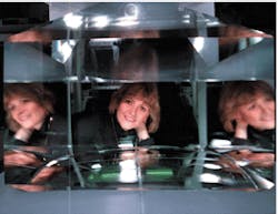
In 1994, LLNL began working with the Russian pioneer of a rapid-growth technique for KDP crystals to scale the capabilities of the process up from roughly 10-kg crystal boules to the 200-250-kg crystal boules required for NIF. Last January, that scientist, now at LLNL, and her colleagues displayed a pyramid-shaped 187-kg KDP crystal measuring 52 cm at the base that was grown in six weeks (see Fig. 1).
The fast-growth crystal technology, including two full-size crystallizers, has been transferred to Cleveland Crystals (Cleveland, OH) and Inrad (Northvale, NJ) for a pilot production effort. This technology is applicable to other aqueous and flux-grown crystals, and Inrad has already adapted it to meet a high-volume order for infrared crystals that it could not have met otherwise.
Fine-form finishing
Approximately 80% of the NIF opticals are flats with appreciable finishing costs, even though the required technology is relatively mature. To target this second-highest optics cost center after the laser glass blanks, the NIF optics team funded three development subcontracts for plano optics fabrication, and another for aspheric lens fabrication. Contracts were awarded to Eastman Kodak Co. (Rochester, NY), Zygo Corp. (Middlefield, CT), and Tinsley Laboratories (Richmond, CA), now SVG Tinsley.
Zygo developed fast fixed-abrasive grinding with electrolytic in-process dressing, initially fabricating 6-in. samples of FS, BK-7, and phosphate glass, and then full-size parts. Mesh numbers were substantially higher than with conventional fixed-abrasive capabilities.4 The NIF application will combine electrolytic in-process dressing with a 61-in. Toshiba vertical rotary grinder for NIF, which extends the maximum-possible dressing-wheel size. Zygo also improved throughput on its planetary polishers.
Tinsley dramatically reduced fabrication times by developing a synthetic pad polisher that processes meter-class flat and spherical surfaces in as little as two hours, as well as a full-scale pellet grinder capable of speeds up to 400 rpm. The company also fabricated the first clad amplifier slab last year with its 1-m lapping and polishing system.
The research by Tinsley and Kodak targeted what is perhaps the greatest impediment to computer-controlled small-tool polishing for high-energy lasers--the very low amplitude (<10 nm) ripple inherent to these processes. Mid-spatial frequency ripple dropped by 10 to 25 times, depending on the process, via Fourier analysis and a rigorous study of the frequency spectra of potential noise sources.
A new language for optics
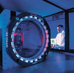
Tying the manufacturing advances to required NIF component specifications also demanded metrology ad vances in areas such as large phase-measuring interferometers (see Fig. 2), coating-conditioning stations and damage test systems (both LLNL designs), and a new device to evaluate large optics for surface-quality defects. This last device, the NIF optics scratch/dig metrology system developed by Display Information Systems (Morgan Hill, CA) requires less than 10 min to scan NIF-sized optics and compare them to the ISO 10110 scratch/dig standard.
Perhaps the metrology-related changes that will have the greatest impact for the optics industry are the changes to the way specifications have been written for the production of optical components for NIF. Most specifications for transmitted and reflected wave-front are still based on parameters easily determined through static-fringe interferometry and stylus profilometry, such as peak-to-valley wave-front errors and rms roughness, although some precision-optics users also require measurement of rms wave-front errors or even Zernicke coefficients. Even these, however, do not encompass the entire wave-front spatial frequency domain to the degree that the NIF specifications for laser components do.
The new specifications--including rms gradients for long-spatial-frequency errors and a combination of power spectral density and rms specifications for mid- and high-spatial-frequency wave-front errors--represent a dramatic departure from tradition. By combining this new language with statistical acceptance criteria, Internet transfer of performance data, and improved modeling capability, LLNL can adjust demands on manufacturers based on an understanding of real laser performance.
To further improve communications between supplier and end user, a new Web-based secure data-management system will serve as the repository for metrology data related to all NIF components--melt information, interferom- etry, surface-quality maps, even coating spectral performance.5 The retention of metrology data, rather than pass-fail criteria, will enable the paradigm shift from the Industrial to Information Age for the optics community. NIF lasers will be constructed using information on a piece-by-piece basis, resulting in the highest laser-system performance possible. o
REFERENCES
1. L. J. Atherton, "Manufacturing Readiness Plan for the National Ignition Facility," NIF-LLNL-94-204, p. 9 (April 1994).
2. J. H. Campbell et al., "Progress on development of continuous glass melting for production of laser glass needed for the NIF and LMJ," UCRL-JC-129804, SSLA Conf., Monterey, CA (June 1998).
3. N. P. Zaitseva et al., J. Crystal Growth 180, 255 (1997).
4. J. K. Lawson et al., in Optical Manufacturing and Testing, V. J. Doherty and H. P. Stahl, eds., Proc. SPIE 2536, 38 (1995).
5. S. Bradley and E. Wheelock, "Using secure World Wide Web technologies to collect and manage optics metrology data," Optical Fabrication and Testing, OSA Topical Meeting, Kona, HI (June 1998).
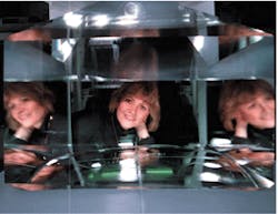
FIGURE 1. Natalia Zeitseva and colleagues at Lawrence Livermore National Laboratory have grown large crystals like this one in less than two months, instead of the year or more required with conventional technology.
FIGURE 2. Phase-measuring interferometers are no longer limited to 18-in. clear apertures, as illustrated by this 24-in. interferometer from Veeco Metrology, formerly Wyko Corp. (Tucson, AZ).


