Optical coatings enhance system performance

Coatings are an increasingly critical component of complex optical systems such as microscopes, telescopes, cameras, and lasers. They can be used to alter the optical properties of system components by increasing or decreasing reflectance, transmittance, absorptance, or polarization. A coating can be a single layer of aluminum applied to glass to produce a flat mirror, or it can consist of multiple layers of oxides, metals, or dielectric thin films that in combination achieve the reflectance or transmittance of a desired wavelength by a process of controlled interference.
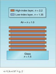
An optical coating is expected to have the dual properties of producing the desired optical effects while improving the hardness and durability of an element, as in plastics or eyeglasses. It is always a compromise between them, says Angus Macleod, president of the Thin Film Center (Tucson, AZ). The individual layers of a coating, the thin films, support interference. The surface of the layers must be completely smooth and parallel so that incident light bounces back and forth between them, allowing the beams to interfere either constructively or destructively with each other.
Modern optical instruments would not function without optical coatings, says David Smith of Opticoat Associates (Chelmsford, MA). In an eight-lens camera, for example, an ordinary glass surface reflects approximately 4% of light. If the optics are uncoated, the cumulative reflection from each lens surface creates a substantial loss of light and adversely affects picture quality through multiple ghost images. To prevent this, each lens in the camera is coated with an antireflection (AR) coating. A highly sophisticated telescope complete with a spectrograph camera might include many AR-coated lenses, plus highly reflective coatings for the mirrors. A microscope, which requires incident light on the sample, will use neutral-density beamsplitting coatings between sample and eyepiece, as well as reflective coatings for mirrors and AR coatings for the lenses.
Coating technology has been around for only 50 or 60 years. Although metal coatings probably originated with Sir Isaac Newton, who made mirrors by polishing highly reflecting metal, interference coatings as we know them today were first made in the 1930s in Germany when sophisticated vacuum chambers were devised (see "Three ways to put on a coat," p. 120). Vacuum science and coating science leapfrogged each other, says Smith. World War II proved to be a boon to the industry. US Army arsenals set up laboratories to make specially coated lenses for binoculars, telescopes, and rangefinders. The difference between seeing with 100% of available light and only 50% of light meant detecting an enemy significantly sooner. "Whoever had better coated optics had the advantage," says Smith.
The beauty of coatings is that you can engineer their behavior, says Angus Macleod. By controlling the type, number, thickness, and sequence of thin films during the manufacturing process, you can define the response of the coating. Coated elements can be used for an almost limitless variety of purposes (see photo). Recently their uses have been extended into short-pulse applications where they can contribute to laser pulse shortening.
Coating materials
Three classes of materials are used in creating coatings: dielectric, metal, and semiconductor. When light enters a material, it interacts with the electrons of that material. Electrons in a dielectric material are bonded very tightly, so the light simply makes them vibrate. This process slows the light down, producing an index of refraction greater than unity. There is no absorption, which makes dielectrics good materials for antireflection coatings. In metals, the electrons are free so the light is absorbed quickly. The high rate of absorption also implies high reflectance, hence metals make good mirror coatings. Electrons in semiconductor materials are not bound as tightly as in dielectric materials, but they are not completely free as in metals. At longer wavelengths, semiconductors act like dielectric thin films with high refractive indices. At shorter wavelengths, the semiconductors act more like metals because the electrons can easily be shaken free. Semiconductors work well for interference coatings in the infrared region of the spectrum.
Coatings take advantage of two primary optical principles, Snell`s law of refraction and the partial reflection of light at an interface. The various beams reflected and transmitted by the interfaces also suffer phase changes, due to their traversal of the thickness of the layers, and they interfere to produce the desired properties. Snell`s Law determines how the properties change with angle of incidence, an important factor in many applications.
For example, consider a quarter-wave optical thickness of a transparent dielectric thin film deposited on a glass surface. At normal incidence there will be reflection from the air-dielectric and dielectric-glass interfaces. The double traversal of the quarter-wave optical thickness makes the two beams 180° out of phase so that they tend to cancel each other and reduce the total reflectance. The optical thickness can be a quarter-wave only at one wavelength. Because of this, the reflectance depends on the wavelength of the incident light. Reflectance can be reduced over a large part of the visible spectrum by a coating designed for a 550-nm wavelength. The reflectance, in this case, is increased in the red and blue, giving the surface a slight purple tinge when viewed in white light. The term blooming is sometimes used to describe the application of this type of coating because the purple tinge resembles the bloom on ripe plums.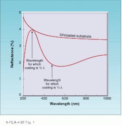
The ability of thin films to perform is also dependent on the angle of incidence. At off-normal incident angles the expressions for calculating reflectance become more complicated and differ increasingly for s- and p-polarized incident light. Angles of incidence up to about 25° mainly shift the reflectance curve to slightly shorter wavelengths. A single quarter-wave-thick (at 550 nm) layer of magnesium fluoride (MgF2) will provide an average of less than 2% reflection at wavelengths between 400 and 700 nm for angles of incidence up to 25° of unpolarized light.
Coatings are vital components of optical systems. They are essential for spectroscopy, medical diagnosis, environmental analysis, quality control, and more recently, ultrafast laser applications. In most cases, because the light is only partially reflected by the various deeper interfaces of a multilayer coating, the resulting reflected pulse is usually broader than the incident pulse. But it is possible to engineer the coating so that either the pulse is not broadened at all or, under certain circumstances, made shorter.
A pulse transmitted through a dispersive medium is longer when it emerges. This dispersive broadening effect can be reversed with a properly designed coating. It is even possible to make an initially long pulse "think" it has been dispersively broadened by a process called "chirping." Such long "chirped" pulses can then be shortened by reflection from a specially designed coating.
Antireflection coatings
Depending on the need, there are many different types of coatings available to choose from. Antireflection implies minimizing reflected and maximizing transmitted light. Antireflection coatings reduce overall transmission loss and minimize stray light by preventing back reflections. Stray light can make a measurement impossible by swamping the desired signal. Reflected laser beams can burn absorbing surfaces, form unwanted foci, and pose safety hazards. Back-reflected beams can destabilize laser oscillators. The proper AR coating is crucial for maximizing system performance.
There are essentially four different classes of AR coatings: single layer, multiple-layer narrowband or V-type, broadband, and special-purpose. Single-layer AR coatings are good for high-refractive-index materials at normal incidence, such as sapphire, Nd:YAG, ruby, and SF10 and SF11 glasses. The V-type coatings typically have two layers and are good for a single laser wavelength or multiple, closely-spaced wavelengths, such as the principal argon laser lines at 488 and 514 nm, the neodymium transitions in a variety of host materials at 1047 to 1074 nm, and the individual excimer laser lines.
Broadband coatings can be optimized for any selected interval in the wavelength range from 193 to 12,000 nm—the wider the specification, the more complex and difficult the coating. The simplest broadband coatings consist of four layers and are designed by inserting a half-wave-thick "absentee" layer of high refractive index into the outermost layer of a V-type coating. This construction design broadens the range of effectiveness of the AR coating to include the visible region. For the lowest possible reflectance at a single wavelength, the V-type AR coating is the best choice, although broadband may provide a wider wavelength range. Special-purpose AR coatings include double-V and triple-V for use in Nd:YAG laser systems at normal incidence (see Fig. 3). Highly damage resistant electron-beam-deposited dielectrics are used virtually exclusively as coating materials in special-purpose AR coatings.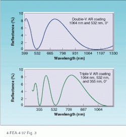
For metal reflector coatings, the main considerations are reflectance, durability, hardness, adherence, uniformity, and long-term stability. When choosing a coating for a beamsplitter, exactly what is being split must be considered. The three basic types of coatings for beamsplitters are dichroic, wavefront or intensity, and polarizing.
Other types of coatings include radically variable reflectors that improve the beam quality of unstable resonators, decorative coatings, cold mirrors that reflect luminous light and transmit heat, heat-reflecting filters, narrowband filters for multiplexing and demultiplexing optical communications signals, and coatings for use as sensors. The list of types and applications is virtually endless.
Coatings of the future
Under development are coatings that will be harder and more resistant to the environment—coatings that will be able to withstand the wear and tear of weather and physical damage. Possible uses are as coatings for scratch-resistant eye glasses and automobile headlights.
Nitrides are being used more frequently as coating technology evolves. Nitrides are compounds of metal and nitrogen that are very tough and durable. Certain compounds are also highly transparent, such as silicon nitride and aluminum nitride, and make good dielectric multilayers. Titanium nitride is gold in color and can be used as a substitute for gold for decorative purposes, for example as coatings on pocket pens and watch bezels.
But much of the research going on at the moment is in processes, especially sputtering, ion-assisted deposition, and other energetic processes that use some form of bombardment. Mid-frequency sputtering, for example, involves driving twin sputtering targets at a frequency around 40 kHz, which avoids many of the problems that exist with more conventional sputtering yet retains most of its advantages because of the relatively low frequency.
Anywhere there is an optical surface, engineers are experimenting with ways to use coatings either to improve performances or to generate a new result. Coating fragments can be used as pigments for automobile paint, as biological sensors, solar filters for investigating the sun, narrow-band infrared filters for sensing dangerous gases, and as interferometer components for sensing gravity waves. Coatings have become an integral part of finished optical systems, without which correct functioning would be limited if not impossible.
ACKNOWLEDGMENT
The author thanks Angus Macleod, Thin Film Center (Tucson, AZ), and David Smith, Opticoat Associates (Chelmsford, MA), for their assistance in preparing this article.
Three ways to put on a coat
There may be many optical coating companies, but there are basically only three processes used to apply coatings: thermal evaporation, ion-assisted deposition, and sputtering. "When it comes to how the coatings are applied, the whole industry is pretty much the same," says David Smith of Opticoat Associates (Chelmsford, MA). "There are similar materials, similar deposition processes."
Thermal evaporation. Perhaps the oldest coating process is thermal evaporation, in which the glass or substrate to be coated is placed in a vacuum chamber. The material to be used as a coating, such as bare gold, is heated at a high temperature under very low pressure, and as it turns to vapor, it expands into the chamber and condenses on the substrate. This physical vapor-deposition coating method (PVD) is repeated for each layer. "A very inefficient process," Smith says. "You end up coating more of the chamber than the substrate."
Using electron-beam sources to heat and vaporize the coating material for thermal evaporation is much more efficient and produces a higher-quality film (see photo). An electron beam of variable voltage and current, from 5 kV to several amps, is concentrated in a very small movable spot in a multi pocket water-cooled copper crucible; each pocket in the crucible can contain a different evaporation material. This method of evaporation is versatile and reduces contamination resulting from interaction between the coating material and the crucible. The heating is localized and easily achieves temperatures high enough to vaporize refractory material.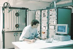
Ion-assisted deposition. Thermal evaporation can give rather poor microstructure, says Angus Macleod of the Thin Film Center (Tucson, AZ). A recently improved method and one that yields a higher quality film is known as ion-assisted deposition (IAD). In this process, while the material is evaporating, the substrate is also bombarded with an ion gun. Charged energetic ions hit the growing film with the mechanical effect of creating harder, more durable layers that are less affected by the environment, last longer, and are more stable. This process is like taking a hammer and hitting the substrate, says Macleod. You are destroying the film columnar structure and squeezing out any voids. This is a more expensive method because of the necessary ion gun, but the rate of deposition is much the same as with straight thermal evaporation, and the improvement in quality at lower substrate temperatures is usually considered worthwhile. The IAD process is often used for coating plastics. In the reactive variant of the process, the ions actually react with the film material.
Sputtering. Then there is the sputtering process, used primarily for conducting materials that can then be reactively transformed into oxides or nitrides. It is particularly useful for continuous processing of wide glass sheets but is also making inroads into batch processing of smaller parts. A substrate and a target of the material to be deposited are placed in the chamber in which a plasma discharge is generated. Heavy ions from the plasma acting like cannon balls bombard the target so that single atoms or molecules are ejected into the vapor phase. These atoms or molecules condense with much greater energy than in thermal evaporation and create a rugged coating (see Laser Focus World, Oct. 1996, p. 63). Sputtering and IAD are just two of the growing number of processes that are classified as energetic because of the additional energy that is involved in the condensation process.
The biggest and most critical part of the coating process does not even involve coating, says Smith. It is cleaning. Each individual optical element is cleaned with an ultrasound cleaner, deionized water, detergents, and solvents before it is coated. "We spend half a day alone just cleaning and inspecting the pieces before we can coat them or else the coating won`t last," says Smith.
Optical engineers can use specialized computer software to calculate the material thickness and number of layers needed for a specified coating. But even with these advanced programs, a person has to be a material scientist as well as an optical engineer when working with coatings, says Macleod. Although the major desired effects are de rived from optical interference, the integrity of the coating de pends on its chemical and mechanical properties. Each layer must adhere to the next and the entire system must stick to the substrate. Short-range chemical bonds hold it all together. Intrinsic strain in the materials stores mechanical energy that can cause cracking or delamination. Reactions with the environment are a major factor in coating failure.
Smith agrees. "To run a coating manufacturing facility," he says, "you have to be an optics engineer, vacuum scientist, and surface chemist. A small optics company probably could not afford to have an in-house staff schooled in all these disciplines."
About the Author
Laurie Ann Peach
Assistant Editor, Technology
Laurie Ann Peach was Assistant Editor, Technology at Laser Focus World.