Diffraction gratings are fundamental optical elements that have a precise pattern of grooves superimposed on them. These minute, periodic structures diffract, or disperse, incident light in such a way that the individual wavelengths making up the incident light can be differentiated. Gratings are indispensable in helping physicists determine the structure of atoms or helping astronomers calculate the chemical composition of stars and the rotation of galaxies. Applications are expanding; one of the fastest growing areas for gratings—laser pulse compression—didn’t even exist until a few years ago.
Joseph Fraunhofer first used diffraction gratings in 1819 to observe the spectrum of the sun. Earliest devices were multiple-slit assemblies, consisting of a grid of fine wire or thread wound about and extending between two parallel screws, which served as spacers. A wavefront that passed through the system was confronted by alternate opaque and transparent regions, so that it underwent a modulation in amplitude.
In 1882, Henry A. Rowland invented the process of ruling, or scratching parallel notches into metal deposited onto the surface of a flat, clear glass plate—a method that produced gratings of exceptionally high quality. Modern ruled gratings can be either reflective or transmissive and are fabricated with a single diamond point that burnishes grooves on flat or concave surfaces.
"The grooves are similar to the indentations made by a plow in soil," says John Hoose of Richardson Grating Laboratory (Rochester, NY), except that they are much closer together. Anywhere from one to 10,000 fine parallel lines per millimeter can be engraved. Light waves diffracted from these lines interfere, and all wavelengths but one are canceled in any particular direction through destructive interference. The depth of the groove changes the wavelength of the light wave being diffracted.
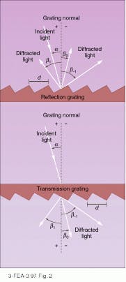
As different wavelengths leave the grating at different angles, they form a spectrum, or diffraction, order. Gratings can produce more than one diffraction order at a time, in a series of ever-wider spectra on either side of a bright central image; referred to as first-order, second-order, and so forth (see Fig. 1), the spectra are caused by interference of a series of waves that are out of phase by one or more wavelengths, respectively. Orders occur when the wavelength of the light diffracted is much smaller than the distance between adjacent grooves on the grating; few occur when the wavelength is comparable to the width of the groove spacing, and none occur except the reflected ray when the wavelength is more than double the groove spacing.Commercial surface-relief gratings are produced using an epoxy casting replication process developed in the mid-1900s. The process involves pouring a liquid into a mold, allowing the liquid to harden, and then removing the hardened material from the mold without damaging either. The replication process yields a grating that is an optically identical copy of the original. The two basic types of grating masters are ruled and interference.
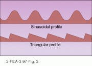
Ruled gratings can be blazed, or shaped, for specific wavelengths. It is harder to achieve specific wavelengths with interference gratings, because the fabrication process does not inherently produce sharp edges and flat surfaces. But because interference, or holographic, gratings are generated optically, less scatter is produced. An interference fringe, or line in the grating, is formed when a photographic plate is exposed to two interfering beams from the same laser. After exposure, the pattern is developed, producing a surface relief master. The groove density can range from 65 to more than 5000 grooves/ mm. Manufacturing difficulties limit most holographic gratings to between 600 and 5000 grooves/mm. Because holographic gratings have a sinusoidal profile, they are not as efficient as ruled gratings (see Fig. 3). However, ion milling, in which the grooves of a holographic grating are bombarded with ions, can change the profile from sinusoidal to "almost" triangular.Grating applications
Light incident on a diffraction grating is dispersed away from the grating surface at an angle dependent on its wavelength, allowing a grating to be used to select a narrow spectral band from a much wider band. This ability of a grating is particularly useful for laser tuning, especially in the visible region of the spectrum. Two primary configurations for selecting a narrow wavelength are Littrow and Littman. In the Littrow configuration, the wavelength of interest diffracts at exactly the same angle as the light incident on the grating. Littrow tuning is done either with fine-pitch first-order gratings (typically 1800 or 2400 grooves/mm, either ruled or holographic) or a coarser grating used in higher orders. The alternative approach is to use the grating in a fixed grazing incidence mode together with a rotating reflecting mirror.
Pairs of diffraction gratings can also be used to compress or stretch a laser pulse. When a spectrally broad laser pulse is incident on a diffraction grating, the various wavelengths that make up the pulse will diffract from the grating at angles determined by those wavelengths. If the pulse is chirped so that the frequency changes linearly during the length of the pulse, then diffraction will spread the pulse out across the second grating. When the light diffracts from the second grating, which is oriented parallel to the first grating, the different parts of the pulse will diffract at angles that yield a pulse whose parts are synchronized. This increases the peak power while the total energy remains the same. Pulse compression uses two gratings with the same groove frequency and efficiencies peaked for the polarization and wavelength of the laser.
If the gratings are arranged in a nonparallel arrangement, a pulse can be stretched. Pulse stretching uses two identical gratings, allowing lower peak power to be transmitted through the laser system and increasing the amount of stored energy that can be extracted.
Since the invention of the replication technique, diffraction gratings have replaced prisms in many commercial spectrometers. A prism will bend short wavelengths more than longer ones (see Laser Focus World, Jan. 1997, p. 101). Prisms that transmit visible light absorb most UV and infrared wavelengths, whereas reflection gratings can be suitably coated for high reflectivity in wide spectral regions. Gratings are considered superior to prisms in many applications. Seeking to combine the best of both, Richardson Grating Laboratory has fabricated a "grism," a part-grating, part-prism optical element useful in spectrometers that require in-line presentation of the spectrum, as in astronomy. The light diffracted by the grating is bent back in line by the refracting effect of the prism. The dispersion of the grism is not linear, because the dispersive effects of the prism and grating are superimposed.
New fabrication techniques
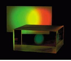
Kaiser Optical Systems Inc. (KOSI; Ann Arbor, MI), has developed an alternative to the classical or surface-relief holographic grating--the volume transmission holographic grating (see photo at top of this page; also Laser Focus World, Oct. 1995, p. 95). The grating is created in the traditional manner by recording interference patterns generated by two mutually coherent laser beams. After the pattern is defined in the photosensitive material, coated on glass, and the film developed, a top layer of glass is added, creating a totally transparent grating assembly. Light strikes the grating on one side and diffracts out through the other.
An advantage of a transmission volume grating is its relative insensitivity to angle, says James Arns of KOSI. A Bragg-type structure follows the classical grating equation concerning image position but with the added ability to adjust the intensity profile over a range of wavelengths. To describe the capability, Arns compares a Venetian blind to lines painted on a window. When the blind is positioned with the slats horizontal, it diffracts light in the same way as the painted lines or a surface-relief grating. When the slats are angled, the element of depth is added to how the light is diffracted. Because of this added dimension, the grating efficiency can be adjusted over the wavelength bandwidth to favor one side or the other. Also, the low sensitivity to incidence angle means the grating can be angularly tuned without influencing the image position.
"It also has a high efficiency," says Arns. "Depending on the configuration, the grating can produce 90% efficiency in the first order. If the thickness or the frequency of the grating is high enough, higher orders that otherwise might be propagated are extinguished." Another advantage, says Arns, is that the element can be handled and cleaned in the same fashion as a high-quality cemented lens because the grating is sandwiched between two layers of glass. Also, because the Bragg-type grating is a transmission device, optical elements and instruments can be brought close to it, resulting in a compact design.
Holoplexing, a technique devised by KOSI in which two gratings are placed together in the same structure to cover multiple spectral ranges at one time, is useful for imaging on charge-coupled-device (CCD) cameras for broadband applications. Holographic transmission gratings are also used in Raman spectroscopy and for pulse compression in ultrafast lasers.
Holographic gratings can also be made from computer-generated interference patterns. The patterns are written onto a chrome mask using an electron-beam machine. The patterns on the mask are then etched into a material, such as fused silica, using photolithographic masking and etching techniques. "Computer-generated gratings have really just reached maturity within the last two years," says Michael Feldman, of Digital Optics Corp. (Charlotte, NC). "They are very flexible and easy to mass-produce."
Their versatility offers many advantages. "Ruled and holographic gratings are limited to relatively simple structures by the fabrication methods that are used," says W. Hudson Welch, also of Digital Optics. "The flexibility provided by computer-generated gratings allows the creation of essentially arbitrary grating patterns."
Fiber gratings
Fiber Bragg gratings, another recent development in grating applications, are made within a fiberoptic cable. Fiber gratings are fabricated by exposing the core of a single-mode fiber, 8 to 10 µm thick, to a periodic pattern of intense ultraviolet light. This pattern is created when a 248- or 193-nm laser passes through a special diffractive phase mask. When a fiber is placed in the intense UV light pattern of the mask, a permanent modulation of the index of refraction is generated in the fiber core. This photo-generated index modulation acts as a grating.
Light traveling along the fiber core impinges on the grating, and each area of different refractive index scatters a small portion of the beam. If the wavelength of the signal is twice the distance between the periodic refractive elements (typically <1 µm), then the signals scattered back down the fiber core will add constructively to give a large reflection. The wavelength at which the reflection occurs is the Bragg wavelength. A Bragg grating can operate at precise wavelengths that can be accurately preset and maintained, says Keith Brundin at 3M Specialty Optical Fibers (West Haven, CT).
There are also long-period fiber gratings that have index modulations with periods of hundreds of microns (see Laser Focus World, June 1996, p. 293). Instead of producing a reflected signal, these gratings create a phase-matching, or Bragg, condition that couples a forward-traveling signal into forward-traveling cladding modes. The signals coupled into the cladding are absorbed by the coating, creating a loss. Long-period gratings thus act as wavelength-selective absorption filters and are used in wavelength-division-multiplexing networks and in gain-shaping filters for rare-earth-doped fiber amplifiers.
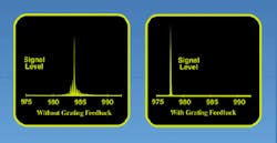
Fiber Bragg gratings have been commercially available only since 1995. They are becoming increasingly popular in telecommunications and the laser industry for such applications as external reflectors for stabilizing semiconductor lasers (see Fig. 4) and single- frequency fiber lasers.The concept of diffraction gratings is simple, yet elegant. For more than one hundred years, they have been used in dispersive optical systems. Applications for gratings are expanding as the fabrication technology grows. Fields as diverse as telecommunications, astronomy, microlithography, lasers, and metal analysis are driving these changes.
ACKNOWLEDGMENT
The author wishes to thank John Hoose of Richardson Grating Laboratory (Rochester, NY) for his help in preparing this article.
