Many applications require the measurement of low-level signals that may be obscured by electrical noise. Tasks associated with such signal processing include measuring, monitoring, and recording the particular frequency of interest. In these experiments, the instrument "locks in" the desired frequency, selecting it from all the other electrical signals. Output from this instrument is an amplified dc signal, proportional to and converted from the initial ac input.
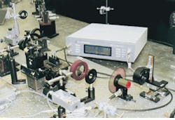
Lock-in amplifiers are used in many different fields. One of the most common applications and one of interest to many laser users is spectroscopy—recovering small optical signals electrically. Other fields in which measuring minute ac signals is important include superconductivity, cryogenic research, industrial quality control, as well as research in astronomy, chemistry, physics and biology (see Fig. 1).
This Product Focus examines some decisions a user of lock-in amplifiers must make to select the proper instrument for an application. Frequency ranges, dynamic reserve, digital-versus-analog signal processing, and single-versus-dual-channel devices will be discussed. Packaging and OEM considerations will also be addressed, including provision of a "lock-in amplifier on a board." A partial listing of manufacturers of lock-in amplifiers and representative products follows on p. 138. A more complete listing is available in the 1996 Laser Focus World Buyers Guide beginning on p. 311.
Theory of operation
Lock-in amplifiers use a phase-sensitive detection technique to sort a desired signal from other obscuring noise sources. Detection is achieved by using a reference signal, usually a sine wave, at the specific frequency and comparing it to the desired signal. Comparison involves multiplication, because, unless the two frequencies are identical, the average of the product of two sine waves is zero. The phase-sensitive detector (PSD) performs the multiplication as part of the lock-in amplifier, driving the noise to zero and singling out the frequency of interest.
The amplifier initially adjusts the gain of the incoming signal, then, using the PSD, multiplies it by the internal lock-in reference signal. The output signal passes through a low pass filter, which removes the ac signals, leaving a dc signal that is proportional to the initial signal amplitude.
Analog vs. digital signal processing
A clear way of demarcating the types of lock-in amplifiers is to find out how the signal is processed. Analog processing is the traditional method; it has been used for more than 25 years. In analog processing, the initial input and reference signal are both analog voltage signals. Multiplication is performed in an analog multiplier and then filtered using resistance-capacitance filters.
Several years ago, digital-signal processors (DSPs) were incorporated into lock-in amplifiers. In a digital device, the initial and reference signals are represented numerically, having been converted via an analog-to-digital (A/D) converter. Multiplication of the reference signal by the incoming data stream is done by the PSD as a series of discrete data points, which are treated mathematically.
Digital devices provide several benefits compared to analog instruments. The internally generated reference sine wave is much cleaner, missing the harmonics that would be present in a square-wave multiplying lock-in. The digital signal reduces other forms of error as well, including output drift (as a function of changes in temperature) and amplitude or gain variations. Analog lock-ins still have their advocates, in part because of familiarity, in some cases because of cost (although that differentiation has virtually disappeared), and because analog lock-ins can continuously change the output in response to the incoming signal. Digital lock-ins require time to update the converter. In experiments with a very short time constant, such as double demodulation, the analog device may be a better choice because it is more responsive and does not introduce updating errors.
Several manufacturers provide lock-in amplifiers that are combinations of both the analog and digital technologies. The analog board is engaged in the low-frequency regime, with the instrument automatically switching to the DSP for the high frequencies. One system even provides a means for using two detectors, so that signals can be detected from the UV to the IR without switching setups.
Selection questions
An initial question that a user must address is the desired frequency range over which the experiments or work will be performed. The typical range is from 1 mHz to 100 kHz. Digital models are also available with an extended frequency range, from 100 kHz to 200 MHz. Analog models additionally provide frequency ranges from 0.5 Hz to 100 kHz.
Another important factor is the dynamic reserve of the lock-in amplifier. Dynamic reserve, measured in decibels (dBs), is the ratio of the largest tolerable noise signal to the full-scale signal without overload—an indication of how well the lock-in amplifier can recover a signal that is buried in the noise. Generally speaking, the larger the dynamic reserve, the better the lock-in amplifier. The trade-off to using ultrahigh dynamic reserve is the increased output noise caused by the noise of the A/D converter. Analog lock-ins usually have a smaller dynamic reserve than do digital instruments. Manufacturers compensate for this limitation by using analog prefilters (tunable bandpass filters) at the input. Again, the trade-off is that the filter adds its own noise and can contribute to phase errors, so these filters should be used only when necessary.
A researcher has a wide variety of lock-in display options from which to choose, depending upon the requirements of the experiment. Some devices have only LED displays showing current values; the more expensive versions include a small CRT upon which the data can be displayed in bar graphs, strip charts, tables, or circular plots. Some units come with built-in memory and storage so that calculations, including statistical analysis and data reduction, can be performed on-board or stored for later processing. Most systems come standard with RS-232 and GPIB (IEEE-488) computer connections. Printer connections are also important.
Some high-end machines also have preprogrammed or automatic functions. Certain optimization routines and common measurement functions are available with a single key stroke. The machines also can be self-programmed and controlled through a computer interface. This feature allows several lock-in amplifiers to be linked together, each controlled independently. Built-in or furnished software packages provide an easy way to start up quickly.
Costs and advice
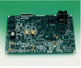
Traditionally, analog instruments have been less expensive than digital ones, but digital-device prices have been coming down, so reverting to an analog instrument is not usually a cost-saving measure. Manufacturers have provided a less costly alternative: a lock-in amplifier on a board (see Fig. 2). This is usually not a board that would be installed in a computer, because a computer is too noisy electrically to facilitate the proper lock-in amplifier operation. Instead, the board could be installed in another piece of equipment, as an OEM might do, or the user could build their own system around the board. A "lock-in on a board" is approximately one-fourth the cost of a similar complete system, however, the user still has a lot of work to do to complete the system.The lock-in amplifier is only one component in the instrumentation necessary to capture and process the desired optical or electronic information. It is important to coordinate the light sources, detectors, computer software, and optical and electronic equipment so that measurements are accurate and errors are either controlled or minimized. In the detection and amplification of very small and obscured signals, it may be helpful to discuss the application with the technical support personnel available at any of the manufacturers, to ensure that the setup measures and amplifies the appropriate signals.

