Computer control makes asphere production run of the mill
Don Golini, Harvey Pollicove, George Platt, Steve Jacobs, and William Kordonsky
Aspheric elements allow complex multielement designs to be dramatically simplified, and they increase the designer`s ability to create optical systems with better performance. An aspheric element can replace two, and sometimes three, spherical elements in a multielement system. For infrared (IR) systems, aspheres can be used because many IR materials are compatible with single-point diamond-turning techniques. In contrast, visible-wavelength systems use brittle optical glasses that are typically unsuitable for single-point diamond turning.
There are no flexible, cost-effective methods for producing general aspheres from these materials. This dilemma has restricted the use of higher-performance optical geometries and has spurred the advancement of optical manufacturing technology.
Despite the higher manufacturing costs of aspheric components, a number of military and commercial systems require these elements. In the Javelin antitank missile-launch unit, for example, the use of aspheric lenses allowed designers to decrease the number of optical elements, reducing weight, size, complexity, and cost while increasing optical transmission and overall performance. The IR material germanium is relatively expensive, so elimination of unnecessary optical elements played a major role in reduction of system costs.
Other optical systems designed for use in military applications that benefit from aspheres include the M1A2 commander`s independent thermal viewer, the line-of-sight antitank forward-looking infrared system, the M1A2 optics system upgrade, the visual and IR channels on the advanced forward artillery system, the future infantry fighting vehicle, I2 goggles, and advanced laser eye protection.
Consumer products such as medical imaging devices, collision-avoidance systems, fiberoptic coupling devices, computer optical data storage, and high-definition television would also benefit from the inclusion of aspheres. An excellent example is the asphere condensor lens element for the Texas Instruments (TI, Dallas, TX) Digital Multimirror Display (DMD) system. Magnification for this system requires extremely high optical resolution. Spherical optics alone cannot meet the stringent requirement, leaving aspheric lenses as the only solution.
The optics industry is in need of an affordable production process for manufacturing aspheres. The elements in demand are not parabolic telescope mirrors, but general high-order glass aspheres for use in traditional visible optical systems. For example, the Center for Optics Manufacturing (COM, Rochester, NY) has received requests from members of the American Precision Optics Manufacturing Association (APOMA) for aspheres ranging from 3 to 50 mm in diameter with aspheric departure ranging up to 12th order with departure values as high as 600 µm. At the same time, these elements require submicron precision. A practical approach for rapidly and affordably prototyping this class of lenses does not exist.
In an effort to satisfy industry demand, COM has collaborated with TI to extend the center`s Opticam computer-controlled grinding systems and magnetorheological finishing (MRF) technologies to fabricate the aspheric elements needed for the DMD projection systems. The curved face of the 47-mm-diameter plano-convex asphere is a hyperboloid with 140 µm of aspheric departure. The figure requirement for this surface was 0.93 µm peak-to-valley (p-v) with a 0.1% tolerance on base radius.
Computer machining of aspheres
The Opticam is a computer-controlled grinding system capable of figuring parts from 10 to 100 mm in diameter (see Laser Focus World, July 1992, p. 146). A high-speed tool spindle drives coarse, medium, and fine diamond wheels to generate high-precision spherical surfaces. Figures of better than one wave p-v with roughness less than 20 nm rms and subsurface damage less than 2 µm are typically achieved. The spherical surfaces, produced in less than 10 min, can go directly to polishing. Centering, edging, sagging, and beveling are all done on the Opticam machine using the same setup.
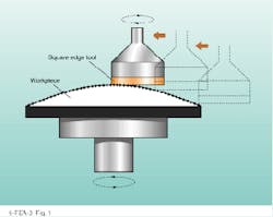
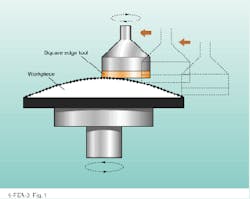
After the plano sides of the TI aspheres for the DMD projection system were finished conventionally, the parts were blocked and machined to the required aspheric geometry on Opticam machines at both TI and COM. This was the first attempt by both organizations to machine aspheres on platforms that were designed and optimized to produce spherical surfaces. A diamond ring tool was used to contour the asphere, stepping across the workpiece from edge to center (see Fig. 1). One tooling approach used the corner of a square edge wheel, while another used the face of a radius wheel.
Using Opticam along with machine alignment strategies developed for the diamond-turning industry, an aspheric figure accuracy of better than 5 µm p-v can be routinely accomplished in less than one hour for a variety of aspheric shapes. Consider a pair of 30-mm-diameter convex hyperboloidal elements recently produced at COM. With 588 µm of aspheric departure, the elements had four times the departure of the TI prescription. After a single 60-min machining cycle on each part, the figure error was measured at less than 3 µm p-v (see Fig. 2).
A residual subsurface damage layer of about 6 µm was left on the part after the surface was machined with a bronze-bonded 15-µm-grit diamond tool. There is currently no need to go to finer grit sizes because the p-v figure error is about the same as the subsurface-damage depth. In the future, when more advanced machine correction strategies are used, form accuracy of better than 1 µm is expected, and new tooling concepts will be required to attain an equally low level of subsurface damage.
Magnetorheological finishing
The TI aspheres were finish-polished using magnetorheological finishing (MRF), a technique recently developed at COM (see photo on cover and p. 83).1 The method is best understood by thinking of the magnetorheological fluid as a compliant replacement for the conventional rigid lap in loose abrasive polishing. Both the magnitude and directionality of pressure applied to the workpiece by the suspension`s abrasive particles are controlled by a magnetic field. When initiated, this field can cause the viscosity and plasticity of the magnetorheological fluid to change from low (soft) to high (stiff).
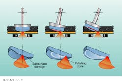
Unlike a rigid conventional lap, the fluid`s shape and stiffness can be held constant for repeatable, predictable deterministic optical finishing. Variable preferential removal is accomplished simply by varying dwell time as a function of position (see Fig. 3). During polishing operations, the workpiece is rotated and swept over magnetorheological "lap," resulting in an annular effective tool path. At present, the method is limited to correction of circularly symmetric errors, though future plans include developing asymmetic correction capabilities.
Magnetorheological finishing uses computer control to reach final optical figure and surface microroughness while removing the subsurface damage left by grinding. Moreover, investigations using hydrofluoric acid etching confirm that the technique does not introduce additional subsurface damage. The MRF computer program is designed to provide polishing solutions for spherical, plano, and aspheric surfaces with equal effectiveness. The technique requires no dedicated tooling or special setup.
Results
As part of the collaborative effort, ten aspheric lens blanks prepared at TI were sent to COM for final finishing. After Opticam machining, the aspheres were measured on a stylus profilometer from Rank Taylor Hobson (Leicester, England), and residual figure errors ranging from 4 to 20 µm p-v were recorded. The MRF program was used to process these error profiles and generate instructions for the finishing machine.
Polishing the parts to reach finish requirements was a two-stage process that included uniform subsurface-damage removal and final figuring. Removal of a 6-µm-thick damage layer typically took about 80 min. Two to four further MRF cycles were usually sufficient to correct the part to meet requirements. Including subsurface-damage removal, average total polishing time was between two and three hours. Typical microroughness of completed parts as measured on a Zygo (Middlefield, CT) scanning white-light interferometer was about 10 Å rms.
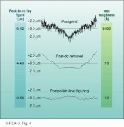
In a sample polishing sequence, an element with an initial postgrind p-v figure of 6.4 µm was improved to 4.4 µm after a 100-min polishing cycle to remove subsurface damage. This also resulted in a 31% error correction. In an additional
40-min figuring run with 81% correction, the aspheric figure error was further reduced to 0.82 µm p-v, meeting specifications (see Fig. 4). All of the parts polished for TI were accepted, and final figure error ranged from 0.66 to 1.8 µm p-v.
Future work with aspheres
Manufacturing advanced optical geometries is the challenge faced by the US precision-optics industry, and COM researchers are aggressively attacking the existing shortcomings of current fabrication processes. The goal of COM is to develop an Opticam Asphere Machine by 1996 that will generate general aspheres to a fraction of a micron precision.
Issues such as residual tool marks, tool wear, machine alignment, process stability, subsurface damage, and cost-effectiveness are currently being addressed. Magnetorheological finishing will meanwhile be optimized toward the COM goal of single-cycle, 95% convergence, with less than l/10 residual surface errors. The combination of these two technologies will offer the optics manufacturing community affordable, flexible optical fabrication technology. n
ACKNOWLEDGMENTS
The expertise, dedication, and teamwork of the people listed here made the asphere project a great success: Mark Atwood, Chris Dewever, Paul Dumas, Ed Fess, Greg Forbes, Gennady Gorodkin, Yuling Hsu, Vladimir Kordonsky, Arne Lindquist, Dave Pietrowski, Igor Prokhorov, Birgit Puchebner, John Schaefer, David Strafford, Alan Tittle, and John Vakiner. MRF has been developed in cooperation with Byelocorp Scientific Inc. and the A. V. Luikov Heat and Mass Transfer Institute, Academy of Sciences, Minsk, Belarus. COM gratefully acknowledges the support of the US Army Materiel Command.
REFERENCE
1. W. Kordonsky, Journal of Intelligent Material Systems and Structures, 4 (1993).
FIGURE 1. A square-edge tool was used on the Opticam computer-controlled grinding machine to produce high-quality aspheres.
FIGURE 2. Form Talysurf traces from two separate 30-mm-diameter convex fused silica aspheres demonstrate the repeatability of the process. The aspheric form was hyperbolic, with 588 µm of departure from the best fit sphere. The figure accuracy was less than 4 µm p-v on both parts.
FIGURE 3. In magnetorheological (MR) finishing the magnetic field (red) creates a highly viscous distribution in the MR suspension (yellow) resulting in a "polishing lap." The rotating part is swept through the subaperture lap. The part dwells longer in the zones where more material must be removed and sweeps quickly through zones where little material removal is required.
FIGURE 4. There are typically three stages in making aspheres using computer-controlled grinding and polishing. To¥graph is surface profile of a workpiece after 200 µm of material was removed in a 70-min Opticam machining operation. Middle graph shows the same piece after 12 µm of subsurface-damage removal in a 100-min magnetorheological finishing (MRF) cycle. Bottom graph is the aspheric surface after a final figuring run using MRF, with an average removal of 4 µm in 40 min.


