ENTERTAINMENT OPTICS: Single-camera, dual-film projector simplifies IMAX 3D recording
Imagine you`re cruising underwater through a waving forest of kelp, fronds trailing past you on either side. A school of spanish mackerel flows gracefully across your path, streamlined bodies gleaming silver in the light. All is tranquil, quiet, and eerily beautiful. Suddenly from nowhere a lifesized shark appears in your lap. You shriek, throw off your headset, and the image dissolves into a fuzzy, harmless pair of sharks 80 feet high. Welcome to the world of IMAX 3D.
The IMAX format was first developed in 1970 as an ultralarge-screen-format film, wowing audiences who were pulled into the images by the sheer size of the 80-ft screen. In 1985, the Imax Corp. (Toronto, Canada) unveiled a dual-camera system for recording three-dimensional (3-D) large-format films. The promise of the technology was subsequently realized as documentaries appeared. Today, narrative IMAX 3D films are popping up, the most recent being Across the Sea of Time, showing in New York City at the Sony IMAX theater in Lincoln Square.
IMAX theater screens are divided into rectilinear (normal perspective) or domical configurations. The rectilinear screens are around 80 ft high and offer the audience members in the center of the theater a 90° field of view. The domical screens (IMAX SOLIDO) offer a 180° horizontal field of view with a 123° vertical field of view. Both screen types can accommodate two-dimensional and three-dimensional format films.
Cameras for shooting the world in 3-D
Three-dimensional or stereoscopic photography requires two images: one from the spatial perspective of the right eye, one from the perspective of the left. Generally, the two images are spaced about 65 mm apart, the average interocular separation of human eyes. During projection, both images are shown. Some means of optical separation (remember the green and red glasses from early 3-D movies?) isolates the left-eye images for viewing by the left eye and the right-eye images for the right, and the image appears in three dimensions.
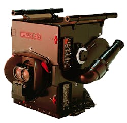
The initial IMAX 3D filming apparatus included two cameras to record separately the left- and right-eye perspectives. The assembly was bulky and heavy and required considerable expertise for the alignment process. Further, an angled mirror/beamsplitter required to bring the two cameras into optical proximity was vulnerable to wind and camera motion. In 1988, Imax began a redesign to produce a turnkey system requiring no optics specialization from the operator. This system was introduced in 1993 (see photo).
Camera optical design
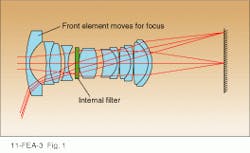
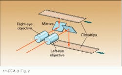
In the new 3-D camera, a single housing contains two objectives that record on separate film strips. These "left-eye" and "right-eye" objectives are separated by 72.4 mm, the closest feasible approximation to the interocular separation of human eyes, given IMAX film frame size and lens diameters. Tests show that this is still sufficient to create the 3-D illusion. The objectives are mounted on a computer-controlled linear slide to provide left-eye/right-eye image quality consistency and extremely precise focusing. For rectilinear projection, Imax offers customized 40-mm, 60-mm, and 80-mm linear Zeiss (Oberkochen, Germany) objectives. Zeiss packages matched pairs of objectives in custom mechanical mounts; focal lengths agree to within 0.1% and pointing accuracy is less than 2 arcmin.
For the IMAX SOLIDO domical screens, a fish-eye lens is needed to capture an adequate field of view. For two-dimensional films, commercially available fish-eye lenses are sufficient. Stereoscopic features, on the other hand, require tight optical tolerances and are highly dependent on the lens spacing. This in turn places a hard limit on the lens diameters; they must be small enough to allow an interocular spacing of approximately 70 mm. Because the available Zeiss lenses had a minimum spacing of 110 mm, Imax was forced to contract out for a custom lens.
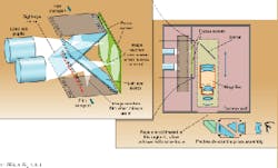
The required high-performance fisheye lens was designed and built by Hughes Leitz Optical Technologies (HLOT, Ontario, Canada). Specifications called for a 150° field of view, an f/number of approximately 3.5, and performance comparable to the Zeiss lens. The most difficult constraint, however, was probably the housing-diameter upper limit of 70 mm imposed by the interocular spacing.The viewfinder can thus be used only when the camera is not running. Beamsplitters would appear to be a solution to the problem, but would limit image intensity at the film plane. "A limited depth of field is unnatural in 3-D," explains Hugh Murray, optics system specialist at Imax. "You want to get as much light in the system as possible so that you can stop down the lenses to maximize your depth of field." Hence the separate filming and viewing features. A parallax-corrected video camera provides in-process viewing, though the error in vertical orientation increases as the point of interest approaches the camera.
The viewfinder is designed such that left-eye and right-eye images are viewed separately. A 45° turning mirror routes the image from the Fresnel focus screen into the relay optics, where a magnifying subsystem can be inserted if desired. A Pechan prism assembly rotates the image so that it is presented upright at the eyepiece of the viewfinder (Fig. 3, right). Focus at the eyepiece can be adjusted to compensate for the vision of the individual camera operator. However, be cause the image has been projected onto the Fresnel focus screen prior to entering the viewfinder optics, such adjustments cannot improve the image beyond that produced by the objectives.
Projection and viewing
During projection of a 3-D feature, the left and right films of the scene must be shown simultaneously but remain isolated for viewing by the corresponding eye. In the standard IMAX system, polarizing filters optically isolate the films. The film for the left eye is linearly polarized with the plane of polarization orthogonal to that for the right eye; both planes of polarization are 45° out from the horizontal. Polarizing filters in the viewing glasses are matched to those of the projector such that the left lens only admits the images for the left eye, and the right lens only admits images for the right eye.
And that is how you might see kelp fronds in your face and a lifesize shark in your lap. Circularly polarizing filters that allow viewers to tilt their heads without losing the illusion might appear to be preferable for the system, but such a system is not feasible. Ken Baker, Imax supervisor of optical and mechanical systems, explains, "Circular polarizers aren`t sufficiently achromatic [for this application]. Generally they're optimized for a single wavelength and fall off to either side. In our tests linear polarizers always win out because of their improved extinction and signal-to-noise capabilities."
In the New York Sony IMAX theater, image differentiation is provided by a more sophisticated system, initially designed for domical screens where variations in the polarization of light reflected from the curved surface precluded the use of polarizing filters. Viewers wear headsets that carry three equidistant infrared (IR) photodiodes and position an individually controlled liquid-crystal shutter over each eye. Driven by an array of wall-mounted IR transmitters synchronized with the film, the shutters alternate between transparent and opaque at a repetition rate of 48 Hz, admitting images to the left eye and right eye in succession. The 3-D image is created and the shark pops up in your lap again, ready for lunch.
Supplemental polarizers included in the system enhance the performance of the shutters and act as backup in the case of detector blockage in the name of scientific inquiry. (Yes, you can cover up all three receivers with your fingers and still see 3-D.) The IR transmitters also send an audio signal to your headset, providing directional sound to complement the visuals.
Three-dimensional films have moved from the realm of novelty to the domain of high technology. Documentaries have given way to dramatic features, and the number of IMAX 3D facilities is growing rapidly. In a few years, who knows, perhaps you'll be able to walk into your local theater to see Arnold Schwarzenegger in 3-D. Just don`t forget the popcorn.
ACKNOWLEDGMENTS
Thanks to Hugh Murray and Ken Baker of Imax Corp., Toronto, Canada, and to Michael Rucker of Sony Theaters, New York, NY, for informative conversations.
About the Author
Kristin Lewotsky
Associate Editor (1994-1997)
Kristin Lewotsky was an associate editor for Laser Focus World from December 1994 through November 1997.


