Light-powered gyroscope has sub-millimeter dimensions
A pair of light waves--one zipping clockwise and the other counterclockwise around a microscopic track--may hold the key to creating the world’s smallest optical gyroscope: one a fraction of the width of a human hair. By bringing this essential technology down to an entirely new scale, a team of applied physicists hopes to enable a new generation of phenomenally compact gyroscope-based navigation systems, among other intriguing applications.1
RELATED ARTICLE: External-cavity semiconductor ring-laser gyro achieves single-mode operation
"We have found a new detection scheme that may lead to the world's smallest gyroscope," said Li Ge, a physicist at the Graduate Center and Staten Island College, City University of New York. "Though these so-called optical gyroscopes are not new, our approach is remarkable both in its super-small size and potential sensitivity."
Ge and his colleagues, physicist Hui Cao and her student Raktim Sarma, both at Yale University (New Haven, CT), published their results in The Optical Society’s (OSA) journal Optica.
More than creative learning toys, gyroscopes are indispensable components in a number of technologies, including inertial guidance systems, which monitor an object’s motion and orientation. Space probes, satellites, and rockets continuously rely on these systems for accurate flight control. But like so many other essential pieces of aerospace technology, weight is a perennial problem. According to NASA, it costs about $10,000 for every pound lifted into orbit, so designing essential components that are smaller and lighter is a constant struggle for engineers and project managers.
If the size of an optical gyroscope is reduced to just a fraction of a millimeter, as is presented in the new paper, it could then be integrated into optical circuit boards, which are similar to a conventional electric circuit board but use light to carry information instead of electric currents. This could drastically reduce the equipment cost in space missions, opening the possibility for a new generation of micro-payloads.
Traditionally, engineers have used two approaches to make optical gyroscopes, both based on the Sagnac effect. The first one uses an optical cavity to confine light and the second one uses an optical fiber to guide light.
The second approach has, to date, been most practical because its sensitivity can be easily enhanced by using longer sections of optical fiber (some up to 5 km long). These lengths of fiber would then be wrapped around an object about 5 cm in diameter, achieving a more manageable size. Though this system is sensitive to rotation, there are practical limits to how long the fiber can be and how small it can be wrapped before the fiber itself is damaged.
To go truly small, optical cavities seem to be the preferable option, where the Sagnac effect manifests as a subtle color change. The problem, however, has been that the sensitivity of this type of optical gyroscopes degrades as the cavity gets smaller.
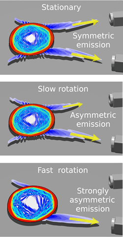
The researchers were able to overcome this hurdle by using a very different principle based on far-field emission. Rather than directly measuring the color change of the light waves, the researchers determined that they could measure the pattern the light produced as it exited the cavity.
"That was our key innovation—finding a new signal with a much improved sensitivity to rotation," said Ge. "Optical gyroscopes optimized to produce and detect this new signal, we found, could be about 10 microns across—smaller than the cross section of a human hair."
To start the new optical gyroscope, light waves are first pumped into the optical cavity. This naturally produces light waves traveling in both clockwise and counterclockwise directions. By carefully designing the shape of the optical cavity, the researchers were able to control where both waves would exit. Normally, cavities are designed to trap light as long as possible. Here, the researchers needed to balance the light trapping properties of the cavity with the need for some light to escape to create a far-field emission pattern. This pattern is observed by placing a pair of camera-like detectors facing the cavity at different angles that move along with the cavity. This allows them to continuously monitor the pattern for distortions that would reveal the speed of rotation.
Though this only reveals one plane of motion, multiple such sensors at different orientations would be able to give a fully three-dimensional picture of how the object is moving.
According to the researchers, further studies are needed to take into consideration the possibility that many modes, or light paths, exist simultaneously in the cavity. Their far-field emission patterns may change in different ways, which causes a reduction of the sensitivity to rotation. The researchers are currently working on different methods to control this effect.
REFERENCE
1. L. Ge, R. Sarma, and H. Cao, Optica 2, 4, 323-328 (2015); see http://www.opticsinfobase.org/optica/abstract.cfm?uri=optica-2-4-323
SOURCE: OSA; http://www.osa.org/en-us/about_osa/newsroom/news_releases/2015/light-powered_gyroscope_is_world_s_smallest_promis/
About the Author

Gail Overton
Gail Overton served as a senior editor for Laser Focus World from 2004 through 2020. She has more than 30 years of engineering, marketing, product management, and editorial experience in the photonics and optical communications industry. Before joining the staff at Laser Focus World, she held many product management and product marketing roles in the fiber-optics industry, most notably at Hughes (El Segundo, CA), GTE Labs (Waltham, MA), Corning (Corning, NY), Photon Kinetics (Beaverton, OR), and Newport Corporation (Irvine, CA). During her marketing career, Gail published articles in WDM Solutions and Sensors magazine and traveled internationally to conduct product and sales training. Gail received her BS degree in physics, with an emphasis in optics, from San Diego State University in San Diego, CA in May 1986.