PANORAMIC OPTICS: Two freeform reflectors control ray bundles exactly

CHRISTOPHER CROKE and R. ANDREW HICKS
In the second half of the twentieth century, it became possible to create optical-quality aspherical surfaces of revolution without much trouble; even more remarkably, in the 1990s the ability to create freeform optical surfaces arrived. Once it became possible to make any surface, the rules changed in the game of designing optical systems. For many purposes it still may be best (lowest in cost, for example) to use spherical lenses. What can be achieved without such restrictions, though, is still revealing itself in the world of optical design.
For one thing, it appears that the full power of partial differential equations (PDEs) for the design of freeform optical surfaces has now been unleashed. PDEs are the dominant way of describing the universe, from Maxwell’s equations to quantum field theory. While the development of a systematic theory is ongoing, the truth is that nobody knows what is going to happen. What we do know is that the past ten years have seen a number of rather surprising examples of what can be achieved with freeform surfaces.
Illumination vs. imaging optics
For example, Vladimer Oliker of Emory University (Atlanta, GA) and his colleagues have produced a complete solution to the illumination problem for a point source. (This problem has a long history, but Oliker provided the first mathematically complete and correct solution, as well as a means of doing numerics.) What this means is that, given an arbitrary image, a reflector can be designed so that if a point source is placed near the reflector then the rays will reflect off of the mirror and onto a plane in such a way that the given image appears.
An important point here is that the design method (and the one we discuss further on) is direct and exact. No optimization is used; an equation is written down and solved. This is fortunate, because representing freeform surfaces requires a lot of parameters and so is not an ideal process for iterative optimization.
Oliker’s work falls in the category of illumination optics, as opposed to imaging optics, which allows one crucial restriction to be relaxed. In imaging optics, each ray emitted by the object must end up at (or, in a real-life design, at least very near) the matching point on the image. In illumination optics, however, what matters is the total energy incident on each target point: as long as the right number of rays ends up in the right places, it doesn’t matter where the rays originated.
To take an elementary example, imaging optics is like lining up a class of children in elementary school by telling each child exactly where to go. Designing illumination optics is more like saying to the children, “Form groups of four kids here, eight kids there, and three kids over there, but we don’t care who is in each group.” With this freedom, it turns out that there is always an exact answer to the point-illumination problem using a single reflector.
Suppose you look at a curved mirror, such as a reflective section of plumbing. You see the world in some complex, distorted way. Now suppose that you want to first pick the distortion and then design a mirror that causes it to happen. Here, we can consider the eye to be a pinhole camera, with the pinhole being a source from which light emanates.
This is a case of imaging optics, where we want each ray to leave the eye, reflect off of the mirror, and go to a precisely described goal point in the scene. It turns out that this problem generally does not have a solution. This is mathematically provable and it essentially boils down to a fact about partial derivatives: Namely, if two functions are given that are supposed to be the partial derivatives of some function, then they probably aren’t. This is essentially the same as saying that a generic field is not the gradient of a potential. Sometimes a decent approximation to this problem, which we call the prescribed projection problem, is possible, but other times it appears that decent approximations don’t exist. Such a situation, and how bad the situation is, is the subject of some of our current work.
Exact solutions using two reflectors
One reflector does not, in general, provide enough freedom to control a single ray bundle—that is, to allow specifying where every ray is to go on a target plane. It turns out, though, that two reflectors can be used to solve this problem exactly. There are some situations where things go sour, but they occur with low probability (although they do have a nasty habit of occurring in very symmetric situations); this problem was solved by the authors in 2010.1
For example, suppose you wanted to look into a two-mirror system and see the world rotated or scaled. That we can do. Note that for a two-mirror system one needs to create a geometry that doesn’t have a single straight axis. The result is more like a periscope or an off-axis telescope such as a Schiefspiegler design.
This problem required more than just some partial differential equations. We used the theory of differential forms to come up with a solution, although this approach can be translated into different languages for other audiences. The numerics are complex and many open problems exist in the generation of these surfaces; for one thing, just picking the right data structures for representing the mirrors is tricky.
In one example (see Fig. 1), two mirrors are designed to scale and rotate a forward scene (a pattern on a wall); a simulation of the view is created with the Persistence of Vision Raytracer (POVRay), a free graphical ray-tracing software package. Seen here is one of the mirrors (the lower mirror of a periscope-like system) and a reflection in it, which is of the upper mirror, which is in turn reflecting a wall in the distance. If an observer looks at the lower mirror from the right position (sadly there is some position dependence), the observer sees the scene in front of the system scaled and rotated.
More exotic examples are possible. Here is where it might strike one that truly unexplored possibilities exist out there. Imagine that we wanted to see a panoramic view in a two-mirror system (and we don’t mean the kind you see when you look into a mirror ball; we mean a true panoramic strip). That too is possible. We have designed a pair of mirrors that does this (see “What are freeform optics?”); a raytracing simulation shows what an observer would see when looking into such a system (see Fig. 2).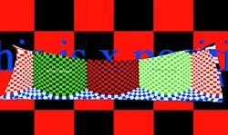
While these systems are interesting, they aren’t fully integrated into image-forming systems. What would be useful is a theory that would include a way to design these systems and could control the size of blur spots. Maybe we’ve been lucky and have been able to design these systems directly without optimization because of the small number of surfaces involved. Perhaps a hybrid technique is best. The answer isn’t clear, but it means that there are a lot of great problems to work on in the design of geometric optical systems.
ACKNOWLEDGMENTS
The first author was supported by NSF DMS 10-03679, and the second by NSF IIS 04-13012 and NSF DMS 09-08299.
REFERENCE
1. R.A. Hicks and C. Croke, JOSA A, 27, 10, 2132–2137 (2010).
Christopher Croke is at the Department of Mathematics, University of Pennsylvania, and R. Andrew Hicks is at the Department of Mathematics, Drexel University (both in Philadelphia, PA); e-mails: [email protected] and [email protected].
What are freeform optics?
Freeform optics are generally thought of as having surfaces that are not only aspherical but have no rotational axis of symmetry. Such surfaces can be produced by diamond turning, certain aspheric grinding and polishing techniques, and molding. Freeform optics can be refractive (for example, certain microscope optics, or elements in optical systems that must see off-axis through transparent missile nosecones) or reflective.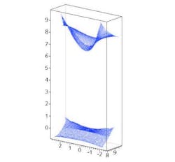
Freeform reflective optics have numerous uses, including in lighting, where they can take light from a nonuniform source and produce either a uniform or properly structured illumination field; or transform an object field of one shape into an image field with another shape, size, or orientation.