NIST measures contamination of EUV lithography optics due to outgassing
Gaithersburg, MD--In the effort to identify and characterize the factors that cause contamination of extreme-UV (EUV) lithography optics, researchers at the National Institute of Standards and Technology (NIST) are relying on two types of optical tests. Spectroscopic ellipsometry is very sensitive to variations in optical properties, while x-ray photoelectron spectroscopy (XPS) reveals the atomic composition of contaminants and some information on their chemical state. Both these techniques are helping the researchers to find and eliminate chemical contaminants on an EUV scanner’s Bragg-reflector focusing mirrors and elsewhere in the system—contaminants that result from outgassing of materials in the system’s vacuum chamber that are the fixed in place on the optics by the 13.5-nm-wavelength exposure light.
Wafer scanners that rely on EUV radiation to expose wafers will allow chip manufacturers to create chip features only 10 nm in size (the conventional minimum is 22 nm); these optical systems must operate in a vacuum, because air absorbs EUV radiation.
Making EUV mirrors last
As a rule, the EUV focusing mirrors are expected to last five years and decrease in reflectivity no more than 1% in that period. Innovative in-situ cleaning techniques have made that longevity possible for conventional deep-UV lithography—but the EUV regime raises new questions. "How can we gauge how long they're going to last or how often they will have to be cleaned?" says Thomas Lucatorto, leader of the NIST Ultraviolet Radiation Group. "Cleaning is done at the expense of productivity, so the industry needs some kind of accelerated testing."
"You can't even test one of these mirrors until you know how everything outgasses," says NIST physicist Shannon Hill. "Ambient hydrocarbon molecules outgassing from all the components will adsorb on the mirror's surface, and then one of these high-energy photons comes along and, through various reactions, the hydrogen goes away and you're left with this amorphous, baked-on carbonaceous deposit."
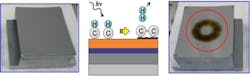
In their tests, the researchers have been using 13.5-nm photons from the NIST synchrotron in a beam about 1 mm in diameter to irradiate a 12-by-18-mm target in multiple places.
"We built a chamber where we can take a sample, admit one of these contaminant gases at some controlled partial pressure, and then expose it to EUV and see how much carbon is deposited," Hill says. The chamber is kept at 10-10 torr before admission of contaminant gases, and the inside surface plated in gold.
"The great thing about spectroscopic ellipsometry," Hill says, "is that it can be done in air and it can map all the spots on the sample in 8 or 9 hours. But being NIST, we're concerned with measuring things accurately. And we've determined if you want to determine how much carbon is present, ellipsometry alone may not be the right way to go—it can give you some misleading answers. XPS is much slower. It takes around 4 hours just to do one spot. But the two techniques give complementary information, so we use both.
Logarithmic, not linear, dependence
"There are several things we wanted to investigate, and one was the pressure scaling of the contamination rate—nanometers of carbon per unit time,” says Hill. “Each spot was made in a very controlled way, at a known pressure and EUV dose. The key thing we started finding is that the rate does not scale linearly with pressure. It scales logarithmically. That's not at all what you'd expect. It's counterintuitive, and it has really important implications for the industry. You could spend millions of dollars designing a system in which you were able to lower the background partial pressure by, say, two orders of magnitude. You would think that you'd done a lot. But in fact, you would have only decreased your contamination rate by a factor of two—maybe."
In addition, PML collaborated with the research group at Rutgers University (New Brunswick, NJ) that was headed by NIST alumnus Theodore Madey until his death in 2008. The Rutgers investigators found, contrary to simple models in which all the adsorption sites have the same binding energy, that in fact the measured adsorption energy changes with coverage. "That is," Hill explains, "as you put more and more molecules on, they are more and more weakly bound. That can qualitatively explain the logarithmic relation we found."
Outgassing of photoresist
In a parallel line of research, Hill, Lucatorto and the other members of the Ultraviolet Radiation Group—which includes Nadir Faradzhev, Charles Tarrio, and Steve Grantham—along with collaborator Lee Richter of the Surface and Interface Group, are studying the outgassing of different photoresists that may be used in EUV lithography.
The outgassing characteristics have to be known in rigorous detail before a wafer and resist can be placed in an EUV wafer scanner. Using another station on the NIST synchrotron's Beam Line 1, they are exposing the photoresists to 13.5 nm light and measuring the outgassed substances both in the gas phase and as they are "baked" by EUV photons on a witness plate.
Source: http://www.nist.gov/pml/div685/extreme-uv-lithography.cfm
About the Author

John Wallace
Senior Technical Editor (1998-2022)
John Wallace was with Laser Focus World for nearly 25 years, retiring in late June 2022. He obtained a bachelor's degree in mechanical engineering and physics at Rutgers University and a master's in optical engineering at the University of Rochester. Before becoming an editor, John worked as an engineer at RCA, Exxon, Eastman Kodak, and GCA Corporation.