SIGNAL PROCESSING: Tilted grating produces true time delay for RF photonics
Microwave-photonic systems are frequently assisted by photonic devices operating at optical wavelengths. For example, true time-delay (TTD) lines, which are essential parts of microwave-photonic signal-processing systems, can be based on IR fiber-optic systems carrying radio-frequency (RF) signals and containing various forms of optomechanical devices to manipulate the RF-signal time delay.
But such devices all have their disadvantages. For example, piezoelectric fiber stretchers have narrow tuning ranges around 10 ps, as well as slow tuning speeds; integrated-optics phase-delay lines have high loss for large bit depths; discrete fiber-Bragg-grating (FBG) delay lines have a very coarse minimum delay increment of 10 ps; and chirped FBG delay lines have group-delay ripple at high frequencies. Other approaches are expensive, slow, noisy, or lossy.
Engineers at the US Naval Research Laboratory (NRL; Washington, DC) have created a continuously tunable TTD line designed to solve these problems. Their device combines a steerable mirror, collimating lens, and diffraction grating to produce a continuously variable optical-path length (see figure).1 The setup is similar to a scanning delay line created for use in optical coherence tomography, with some alterations to the optical system, as well as a concentration on TTD fine-scanning characteristics.
The NRL TTD device is fiber-coupled and has a 75 ps continuously tuned range and a 3 dB optical insertion loss. Its tuning range is large enough to tune over at least one RF period for modulation frequencies of 1 to 100 GHz. It also handles modulated signals well, introducing very little variation in amplitude and group delay across a 4–18 GHz modulation range.
Littrow grating configuration
In the experimental setup, the end of a singlemode fiber is imaged onto a manually steerable gold-plated mirror (the mirror can be replaced with an automated scanning mirror or other form of fast beam deflector for use in production systems). The image point coincides with the mirror's axis of rotation such that the reflected diverging beam, when steered, changes only in angle and not translational displacement. As a result, when collimated, the beam can be translated laterally back and forth with any change in the beam angle.
Rotating the mirror translates the beam across a tilted diffraction grating, which is in a Littrow configuration such that the beam is diffracted back along the path by which it arrives. The path length is an approximately linear function of the position of the beam on the grating.
An achromatic doublet with a 40 mm clear aperture collimated the beam onto a grating with 600 grooves/mm placed at a 27.7° angle to the beam. The TTD device was tested in a photonic link that also contained a 19 GHz Mach-Zehnder intensity modulator, a 1550 nm distributed-feedback laser, an RF amplifier for high-frequency tests, and a photodiode. Because the device had negligible frequency dependence and did not introduce significant optical dispersion, the group delay was the same as the phase delay, meaning that the controllable optical TTD produced a TTD for the RF signal carried by the fiber.
Results showed an RF phase delay that was essentially independent of frequency. The standard deviation of the time delay for various mirror angles was calculated across the 6 to 18 GHz amplifier bandwidth, and ranged from 60 to 160 fs for different mirror angles, which is one to two orders of magnitude better than that for chirped FBG delay lines.
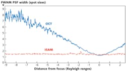
The achromat introduced some spherical aberration into the system, as determined by taking data at two focal positions—the paraxial focus and a second focus near the marginal focus. This limited the delay tuning range to less than the theoretical 140 ps, say the researchers. Better optics would ease this problem. Even so, RF power ripple was less than 3 dB over a 12.8° (76.3 ps) tuning range and less than 6 dB over a 15.8° (94.2 ps) range.
Calculations show that by using a high-quality lens with a 60 mm clear aperture, a delay tuning range of 1000 ps is possible, although larger tuning ranges become impractical due to an awkwardly large optical system.
REFERENCE
1. R.T. Schermer et al., Opt. Exp., 19, 6, 5371 (Mar. 14, 2011).
About the Author

John Wallace
Senior Technical Editor (1998-2022)
John Wallace was with Laser Focus World for nearly 25 years, retiring in late June 2022. He obtained a bachelor's degree in mechanical engineering and physics at Rutgers University and a master's in optical engineering at the University of Rochester. Before becoming an editor, John worked as an engineer at RCA, Exxon, Eastman Kodak, and GCA Corporation.