DEPTH-OF-FOCUS ENHANCEMENT: Simple wavefront-coding setup is adjustable in real time

An optical technique called "wavefront coding," invented by Ed Dowski and Thomas Cathey at the University of Colorado (Boulder, CO) in the mid-1990s, provides a simple, effective way to increase depth of focus in many imaging systems. The technique has found commercial success and remains of interest to researchers.
In wavefront coding, a contoured clear plate is placed at or near the pupil plane of an imaging system; the plate introduces a phase shift that varies cubically across the pupil. The system's resulting point-spread function (PSF) is relatively uniform both across the image plane and through an extended focal range. The plate degrades the PSF somewhat but does it uniformly across the aperture and through-focus; to get a good image, a computer calculation removes most of the degraded PSF effects.
Ed Dowski formed a company called CDM Optics in 1996 to commercialize wavefront coding. Five years ago CDM Optics was acquired by consumer-camera-sensor giant OmniVision (Santa Clara, CA); under the name TrueFocus, wavefront coding has since been integrated into some of OmniVision's products.
While Dowski has continued researching the technique, others have too. A group at Heriot Watt University (Edinburgh, Scotland) has pursued infrared imaging and other optics that use wavefront coding. Now, the Heriot Watt group has reported what it says is the first demonstration of a simple technique using two rotating phase plates to continuously vary the amount of cubic phase shift, allowing optimum adjustments for changing conditions.1 The idea of rotating cubic phase plates with respect to each other to change the amount of phase modulation is actually Dowski's.2 But the Heriot Watt group has created a compact realization of the approach.
Threefold rotational symmetry
Made of fused silica, the two phase plates have clear-aperture diameters of 12 mm and phase-altering surfaces defined by a cubic polynomial with threefold rotational symmetry; the other sides of the plates are flat. The polynomial surfaces are produced through a laser-polishing process. When the plates are placed side by side, the cubic phase shift produced by the combination varies from zero to maximum and back to zero as relative rotation varies from 0º to 120º.
The plates were mounted on rotation stages and placed in front of a 300 mm camera telephoto lens, with a 1.3 Mpixel, 6.7 µm pixel-pitch cooled CCD camera as the image sensor. A spoke target was placed 4 m away and the lens focused on it; for defocused images, the target was moved to a distance 3.5 m away from the lens. Images were captured for various plate-rotation angles, along with images of the in-focus PSF. For the post-imaging calculations, the in-focus PSF was used as the kernel for a Wiener-filter algorithm.
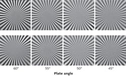
Results for the comparison between the in-focus and out-of-focus images show that a substantial difference exists for a 60º plate rotation (no cubic phase shift); for a 55º rotation, the out-of-focus image is qualitatively as sharp as the in-focus image; and both images are close to the 60º in-focus image in quality (see figure). For larger cubic phase shifts (50º and 45º rotations), the in-focus and out-of-focus images are similar but degraded in comparison to the 60º in-focus image. Thus, for this particular imaging system and focal range, the 55º rotation is optimum.
The advantage of the rotating-plate arrangement is that such phase shifts can be introduced (and varied) in real time.
REFERENCES
1. M. Demenikov et al., Opt. Lett. 35, 12, p. 2100 (2010).
2. E. Dowski, "Mechanically adjustable optical phase filters for modifying depth of field, aberration tolerance, anti-aliasing in optical systems," U.S. Patent 7,180,673 B2 (2007).
About the Author
John Wallace
Senior Technical Editor (1998-2022)
John Wallace was with Laser Focus World for nearly 25 years, retiring in late June 2022. He obtained a bachelor's degree in mechanical engineering and physics at Rutgers University and a master's in optical engineering at the University of Rochester. Before becoming an editor, John worked as an engineer at RCA, Exxon, Eastman Kodak, and GCA Corporation.
