TERAHERTZ IMAGING: Terahertz imaging uses a demodulating detector array

GUNNAR SPICKERMANN
One of the most widely used and flexible ways to get information from light in the terahertz frequency range is to use a femtosecond-laser-based terahertz time-domain-spectroscopy (THz-TDS) system, which is often based on electro-optical detection of terahertz radiation. In this approach, a terahertz electric field is optically detected using the birefringence caused by a terahertz pulse within a nonlinear crystal (typically zinc telluride). Terahertz fields are detected as a change of the polarization state of an optical probe pulse.
This approach has an outstanding bandwidth and is widely used. Unfortunately, the change in optical polarization is extremely small due to the weakness of the underlying nonlinear effect. Moreover, the electro-optic signal is partially masked by a large optical background signal. As a result, the ratio between the modulation amplitude of the signal and the magnitude of the background intensity is very small—usually in the range of 10-6 to 10-9.
In typical TDS systems, this problem is avoided by adopting a differential detection scheme. For this purpose, a circularly polarized optical probe beam is used, and the polarization change is detected by sensing the difference between the intensity in two orthogonal polarizations with a balanced differential photodetector to eliminate the background light intensity. Additional noise suppression is achieved by modulating the terahertz emitter and using lock-in detection. Such systems are widely used, reaching a dynamic range above 110 dB/(Hz)0.5 with typical high-repetition-rate (approx. 80 MHz) unamplified femtosecond lasers.1,2
Electro-optic terahertz imaging
The standard THz-TDS is a single-pixel detection scheme: The electro-optic crystal is probed by a single laser beam at one position only. Such an approach can create terahertz images by scanning an object in a focal plane in the terahertz detection path and sequentially sampling all image pixels.3 This produces excellent results and has been amply reported in the literature, but the image acquisition time is very long due to the serial pixel acquisition.4
Early on, it was recognized that this method could be simply expanded to produce a 2-D terahertz-imaging detector. To do this, the terahertz beam must be modified to project a full 2-D terahertz image onto a large-area electro-optical crystal, sampling the crystal with an expanded probe beam; the optical signal is then detected with a CMOS or CCD camera system.5
To limit the influence of the large signal background, the electro-optic detection crystal is typically placed between two crossed polarizers to enhance the ratio between the terahertz-related polarization change and the optical background. However, the dynamic range achievable at each pixel is very limited due to the need to distribute both the terahertz beam and the optical probe beam power over the detector crystal area. Additionally, optical leakage through the second polarizer easily saturates the camera and decreases the dynamic range available for the detection of the terahertz-induced light-intensity change.
This background cannot be eliminated as it could in the single-pixel setup, because in the 2-D case it is not possible to realize a differential detection scheme. To realize terahertz imaging with CCD or CMOS cameras, it has been necessary in the past to use amplified femtosecond-laser systems. Such lasers generate higher terahertz field amplitudes, and consequently higher optical modulation depths, which enable signal detection and separation from background within the limited dynamic range of CCD or CMOS cameras.
The PMD principle
A new approach to electro-optic terahertz imaging uses a time-of-flight camera as a demodulating detector array instead of a standard CMOS or CCD detector. As a result, sensitivity is much greater: The signal-to-noise ratio (SNR) is increased by two to three orders of magnitude, enabling real-time terahertz imaging with a standard high-repetition-rate femtosecond laser and eliminating the need for amplified laser sources.
The photonic-mixing-device (PMD) camera was developed as a 3-D sensor for robotics and automotive applications.6 It uses an active LED illuminator that emits IR pulses at a modulation frequency of 20 MHz. Objects in the recorded scene reflect part of this active illumination together with unmodulated background from other light sources. The PMD sensor calculates its distance to the objects through a time-of-flight measurement of the light pulses. For this distance measurement, it is vital to precisely measure the phase shift between the light modulation hitting the detector and the reference signal routed internally in the camera.
Because unmodulated background light disturbs the measurement and decreases the dynamic range remaining for the detection of light modulation, such a detector is optimized to sense modulated light and separate it from an unwanted background. The PMD camera can remove most of the background resulting from unmodulated illumination during the optical measurement process, before a conversion to digital data occurs. To achieve this, every pixel in a PMD sensor has two readout channels connected to two integration capacities close to two transparent modulation gates. The modulation gates create a potential gradient under the photosensitive area of the pixel. This gives control over in which of the integration capacities most of the photogenerated carriers are integrated and it is fed with a reference signal having the same frequency of the light modulation to be detected.
PMD camera as demodulating detector array
A PMD camera is very convenient for detecting a weak terahertz-induced optical modulation on a strong background in a terahertz-imaging setup, due to its intrinsic demodulation capability. In our experiment, the beam of a femtosecond laser pulsed at a 76 MHz repetition rate is split into a pump beam for the generation of terahertz pulses and a probe beam for probing a large-area (20 × 20 mm) zinc telluride electro-optical crystal (see Fig. 1). The pump beam is focused onto a semi-large-aperture photoconductive emitter consisting of two photolithographically defined gold electrodes on a semi-insulating gallium arsenide substrate. The structure is biased at 300 V with a 1 MHz sinusoid and optically pumped at an average power of approximately 1.3 W. The emitter produces modulated terahertz pulses with a time-averaged power estimated (using a Golay cell for measurement) to be around 2 µW.
Rather than focusing all radiated terahertz power to a single spot as in a classical terahertz-TDS setup, the terahertz beam is collimated with a Teflon lens to illuminate the sample, which is located in the object plane of a second Teflon lens. This second lens images the object onto the detector crystal, in which the electrical field of the terahertz radiation induces a birefringence distribution in proportion to the terahertz image. The terahertz-induced birefringence is sampled by the expanded probe beam (which has a time-averaged power of 260 mW), leading to the desired intensity modulation of the laser light after passing through a polarization analyzer.7
The PMD principle allows measurement of the in-phase component of the modulation only. To measure the modulation amplitude independently of the phase, the PMD camera measures at four consecutive 90° phase shifts. From the measurements of both read-out channels at four different phase shifts, it is straightforward to derive the modulation amplitude and phase shift relative to the reference signal in each PMD pixel. This allows using the PMD camera as a lock-in detector array for optical signals.
Experimental results
A measurement was taken of the electrical field transient and its spectrum in the pixel detecting the largest field amplitude when no object is in the terahertz beam path (see Fig. 2). Here, the integration time at each time position was 1 s, resulting in a SNR of 40 dB. In addition, a terahertz image is shown as an inset in an optical image of a USAF resolution test target measured with our setup after normalization and numerical correction of wavefront distortion resulting from the terahertz optics. Here we imaged element 6 and part of element 5 of group -3 of a USAF resolution test target. As the original image size recorded by the setup in the vertical direction is smaller (18.7 mm, as well as 14 mm in the horizontal direction) than the shown terahertz image, this is a compilation of multiple images recorded while the test object was moved.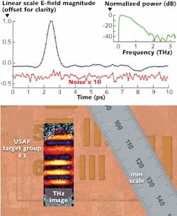
The electro-optic terahertz imaging experiment, with a resolution of 3072 pixels, was realized without the use of an amplified laser source, which limits the peak electro-optic modulation depth to approximately 7 × 10⁻⁵ (referenced to the unmodulated optical background intensity at the detector position). Even so, a SNR greater than 30 dB within a 100 ms integration time was demonstrated.
REFERENCES
1. Q. Wu et al., Appl. Phys. Lett. 67, 3523 (1995).
2. G. Zhao et al., Rev. Sci. Instrum. 73, 1715 (2002).
3. B.B. Hu et al., Opt. Lett. 20, 1716 (1995).
4. P.C.M. Planken et al., Appl. Phys. A 78, 465 (2004).
5. Q. Wu et al., Appl Phys. Lett. 69, 1026 (1996).
6. T. Ringbeck et al., Adv. Radio Sci. 5, 135 (2007).
7. G. Spickermann et al., Opt. Lett. 34, 3424 (2009).
Gunnar Spickermann is a research scientist at the Institute of High Frequency and Quantum Electronics at Siegen University; Hoelderlinstr. 3, 57076 Siegen, Germany; e-mail: [email protected]; www.hqe.fb12.uni-siegen.de.