Record high output power generated from ytterbium-doped fiber amplifiers above 1150 nm has been achieved in a solid-core photonic-bandgap fiber. The photonic bandgap inhibits the growth of amplified spontaneous emission, which normally limits the power scalability at long wavelengths with low gain.
CHRISTINA B. OLAUSSON, JENS K. LYNGSØE, JES BROENG, HIROKI MARUYAMA, and AKIRA SHIRAKAWA
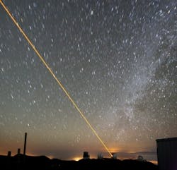
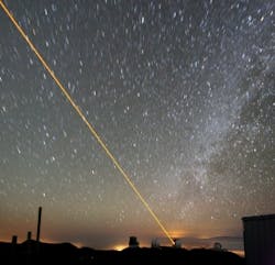
Lasers and amplifiers operating in the 1150-to-1200 nm wavelength range have been extensively developed, typically using bulk solid-state laser technology. Frequency doubling of these wavelengths produces yellow-orange light from 570 to 600 nm—a region useful for various medical applications, for high-resolution spectroscopy, in atomic physics, and in laser-guide-star facilities. For example, in laser-guide-star applications, a yellow laser produces a bright spot in the sky that is used as a reference point for adaptive optics to correct for atmospheric distortion (see Fig. 1). This glowing artificial star is created by exciting sodium atoms in the mesosphere, and requires a high-power diffraction-limited source at 589 nm.1
FIGURE 1. At the Keck Observatory in Hawaii, a laser beam is projected into the night sky to create a sodium beacon guide star. (Photo by Paul Hirst, http://en.wikipedia.org/wiki/File:Keck_laser_at_night.png)
In the past, solid-state or dye lasers have been used for guide stars; however, fiber-laser sources have advantages over these lasers in terms of low operating costs, high beam quality, and high efficiency in a reliable and compact format. Frequency doubling of Raman fiber lasers and bismuth-doped lasers has been investigated for this purpose.2, 3 One drawback is that these lasers need core pumping with a 1 &nicro;m high-brightness source, which is both more expensive and less efficient than cladding pumping with 976 nm diode lasers. In addition, Raman fiber lasers suffer from bandwidth broadening, which results in low conversion efficiency in the frequency-doubling stage. Long-wavelength ytterbium-doped fiber lasers containing fiber Bragg gratings have also been investigated for frequency doubling.4
The photonic-bandgap fiber solution
One of the more promising candidates is an air-clad ytterbium-doped solid-core photonic-bandgap (PBG) fiber amplifier, for which as much as 30 W of output power and a slope efficiency of 58% have been achieved at a 1178 nm wavelength.5
Ytterbium-doped silica fibers in general have a very broad fluorescence spectrum extending up to 1200 nm. The net small-signal gain can exceed 10 dB at 1178 nm; however, the large gain between 1030 to 1100 nm creates very strong amplified spontaneous emission (ASE) and leads to parasitic lasing, limiting the available gain and thereby the power scaling.
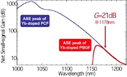
Combining an ytterbium-doped core with the wavelength-filtering effect of PBG confinement results in efficient suppression of ASE at the conventional ytterbium gain wavelengths and thus a reduction in parasitic lasing outside the bandgap (see Fig. 2).
FIGURE 2. The signal gain in a traditional ytterbium-doped photonic-crystal fiber (PCF) is small compared to that in an ytterbium-doped photonic-bandgap fiber (PBGF).
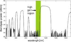
Peak amplification occurs at the wavelengths that experience the least loss due to the bandgap combined with the highest gain due to their emission cross section. Thus, the position of the bandgap relative to the high-gain region is crucial to the efficiency of the amplifier (see Fig. 3). The position of the bandgap, and thereby the position of the ASE peak, can be shifted toward longer or shorter wavelengths by rescaling the dimensions of the fiber. When the fiber is bent, the bandgap narrows and the short-wavelength edge red-shifts faster than the blue-shift of the long-wavelength edge. This is a characteristic property of PBG fibers and can be used to fine-tune the position of the bandgap.
FIGURE 3. A transmission spectrum shows the position of the bandgap relative to the high-gain region, where the ASE suppression is necessary.
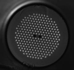
The PBG fibers fabricated for this purpose have cladding pitches that fall between 9.45 and 10.1 µm (see Fig. 4).6 The signal core consists of an ytterbium-doped rod, which is index matched to the silica background. The core is surrounded by a PBG pump cladding structure composed of eight rings of high-index germanium-doped rods. The diameter of the PBG pump cladding is measured to be between 214 and 225 µm. Furthermore, the pump cladding is surrounded by an air-clad structure that provides the pump guide with a large numerical aperture (NA) of 0.57, allowing for efficient high-power cladding-pumping.
FIGURE 4. The PBG fiber structure is imaged under a microscope. The lighter regions are the germanium-doped rods that constitute the pump cladding, while the two darker regions are the boron rods. The pump-cladding structure is surrounded by an air cladding. (Courtesy of Crystal Fibre)
The polarization-maintaining properties of the fiber are obtained by incorporating two low-index boron-doped rods on either side of the core. The boron-doped rods act to apply stress, inducing a birefringence on the order of 10-4 in the fiber. The low refractive index of the boron rods results in confinement by total internal reflection in the direction of the boron rods, while maintaining bandgap guiding in the orthogonal direction.
Low losses
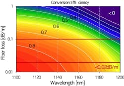
Based on general theories of energy extraction in gain media, the ratio of small-signal gain to loss should be greater than 10 to achieve at least a 50% extraction efficiency; hence, for high-efficiency operation, the loss in the bandgap is required to be much lower than 0.1 dB/m (see Fig. 5). Thus, creating highly efficient PBG fiber amplifiers in the region from 1150 to 1200 nm is a great challenge.
FIGURE 5. Conversion efficiency (isolines) are plotted as a function of fiber loss and wavelength. With losses below 0.1 dB/m, an efficiency of 50% can be obtained at 1178 nm, while an efficiency of 68% can be obtained with losses below 0.02 dB/m.
The loss in the bandgap for a first version of the fiber has been measured to be below 0.1 dB/m, and to approximately 0.02 dB/m for a later version fabricated with an improved drawing process. The loss outside the bandgap was too high to be measured accurately. The loss characteristics of the fibers yield sufficient gain at long wavelengths combined with perfect suppression of ASE in the high gain region, making these fibers very well suited for efficient long-wavelength amplification.
A fiber from the first draw was used in a 1156 nm amplifier, while a fiber from the improved process was used in a 1178 nm amplifier. The optimal fiber length was calculated based on loss measurements for both 1156 nm and 1178 nm operation, and while 24 m of fiber is optimal for the 1156 nm amplifier, a much longer fiber of 37 m is required for the 1178 nm amplifier.
Record powers
In the experiment, unpolarized Raman fiber lasers at 1156 and 1178 nm were used as seed sources. The amplifiers were backward-pumped using a 976 nm diode laser. A fraction of the pump light is inevitably trapped in the high-index germanium rods, although this phenomenon can to a large extent be avoided by off-axis pumping. This type of pumping is only possible due to the high NA air-clad design. However, approximately 12% of the pump light is expected to remain in the germanium rods in the experiment.
In the 1156 nm amplifier, the maximum output power was 32 W with a slope efficiency of 66%—a record power output for a PBG fiber.7 Even more striking is the high slope efficiency. Considering the pump light trapped in the germanium rods, the slope efficiency was estimated to be as high as 75%. The output power was only limited by the available pump power.
An attempt to use the fiber in the 1156 nm amplifier at 1178 nm resulted in a slope efficiency of 33% and the onset of parasitic lasing at 9.1 W. As a result of the propagation loss and shorter length of this fiber, the upper-state population of the ytterbium ions was not sufficiently depleted, causing a growth of ASE gain.
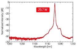
The length and lower losses of the 1178 nm amplifier dramatically improved the performance to a maximum output power of 29.7 W and a slope efficiency of 58%, or 66% if trapping of pump light in the germanium rods is considered. The output spectrum showed no sign of ASE, indicating potential for further power scaling (see Fig. 6). The beam quality M2 was measured to be less than 1.1. Polarization-maintaining amplification was also successfully demonstrated by incorporating a linear polarizer before seeding the amplifier. A maximum output power of 25.3 W was obtained with a slope efficiency of 56% and a polarization-extinction ratio of greater than 13 dB.
FIGURE 6. A spectrum of the 29.7 W output shows no sign of ASE.
The results obtained with this fiber are, to our knowledge, the highest output powers generated from PBG fibers or from ytterbium fiber amplifiers at these long wavelengths. Furthermore, the power scalability, good beam quality, and polarization characteristics make this fiber exceptionally promising for applications such as laser guide stars. The future European Extremely Large Telescope will require multiple diffraction-limited 589 nm sources with more than 50 W output power; we believe a PBG fiber-based solution will be preferable for this next-generation laser-guide-star facility.
REFERENCES
1. N. Saito et al., Opt. Lett. 32, p. 1965 (2007).
2. Y. Feng et al., Jpn. J. Appl. Phys. 43, p. L722 (2004).
3. A. B. Rulkov et al., Opt. Express 15, p. 5473 (2007).
4. J. S. Sinha et al., Opt. Lett. 31, p. 347 (2006).
5. A. Shirakawa et al., Opt. Express 17, p. 447 (2009).
JES BROENG is a researcher at Crystal Fibre, Blokken 84, DK-3460 Birkerød, Denmark; CHRISTINA B. OLAUSSON and JENS K. LYNGSØE are at Crystal Fibre and are graduate students in the Dept. of Photonics Engineering, Technical University of Denmark. AKIRA SHIRAKAWA is a professor and HIROKI MARUYAMA is a graduate student at the Institute for Laser Science, University of Electro-Communications, 1-5-1 Chofugaoka, Chofu, Tokyo 182-8585, Japan. E-mail Christina Olausson at [email protected]www.crystalfibre.com
